Vehicle power device and wheel bearing device with generator

a technology of power device and generator, which is applied in the direction of vehicle sub-unit features, braking discs, transportation and packaging, etc., can solve the problems of high manufacturing cost, need to be regularly replaced, and complicated structure, and achieve the effect of eliminating potential differences, high manufacturing cost, and simple structur

Active Publication Date: 2020-07-30
NTN CORP
View PDF0 Cites 1 Cited by
  • Summary
  • Abstract
  • Description
  • Claims
  • Application Information

AI Technical Summary

Benefits of technology

[0007]The configuration described in Patent Document 1 is applicable only to a vehicle drive device that includes a motor of an inner rotor type as a driving source. In addition, an electrolytic corrosion prevention unit for pressing a contact body against a rotor includes a large number of components, resulting in a complicated structure and high manufacturing costs. Thus, the configuration shown in FIG. 15 includes conducting brushes Br provided between a stationary ring and a hub flange of a wheel bearing in order to make it applicable to a vehicle drive device that includes a motor of an outer rotor type as a driving source. In this case, the conducting brushes Br conduct electric current where a potential difference is generated between inner and outer rings of the wheel bearing so as to eliminate the potential difference and thereby prevent electrolytic corrosion caused by a spark at a rolling element 60. The conical surface or spherical contact body or the conducting brushes Br, however, needs to be regularly replaced because their current conduction performance would be deteriorated due to friction caused by continuous sliding during rotation of the wheel bearing.
[0008]An object of the present invention is to provide a vehicle power device and a wheel bearing device with a generator that are capable of preventing electrolytic corrosion of a wheel bearing and eliminating necessity to perform maintenance for an insulating function.

Problems solved by technology

In addition, an electrolytic corrosion prevention unit for pressing a contact body against a rotor includes a large number of components, resulting in a complicated structure and high manufacturing costs.
The conical surface or spherical contact body or the conducting brushes Br, however, needs to be regularly replaced because their current conduction performance would be deteriorated due to friction caused by continuous sliding during rotation of the wheel bearing.

Method used


Image

  • Vehicle power device and wheel bearing device with generator
  • Vehicle power device and wheel bearing device with generator
  • Vehicle power device and wheel bearing device with generator

Examples


Embodiment Construction

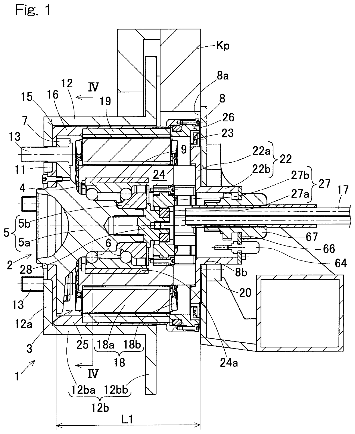
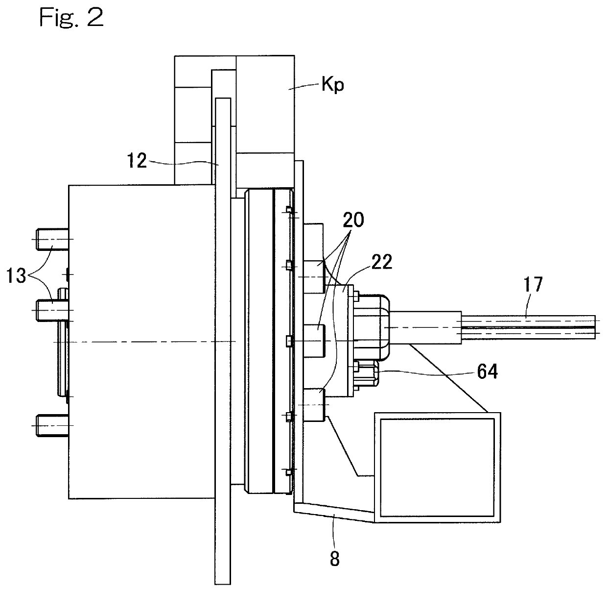
[0058]A vehicle power device according to an embodiment of the present invention will be described with reference to FIG. 1 to FIG. 5. As shown in FIG. 1, the vehicle power device 1 includes a wheel bearing 2 and a motor generator 3, i.e., a generator that also serves as a motor. It should be noted that the wheel bearing device with a generator according to an embodiment of the present invention may include the vehicle power device 1 having a generator that does not serve as a motor, instead of the motor generator 3. That is, the wheel bearing device with the generator includes a generator 3 that does not serve as a motor and a wheel bearing 2. The wheel bearing device with the generator has the same configuration as that of the vehicle power device 1, except for the motor generator 3 that also serves as a motor.

[0059]Wheel Bearing 2

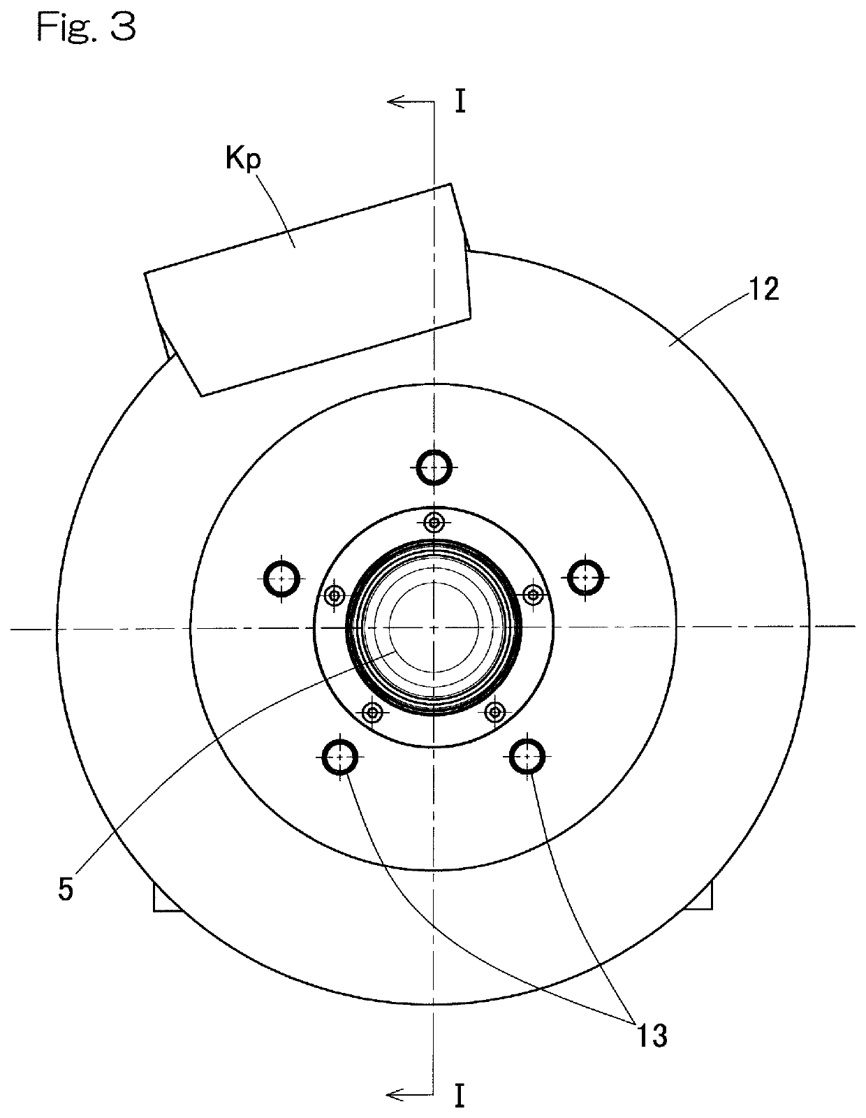
[0060]The wheel bearing 2 includes an outer ring 4 as a stationary ring, double-row rolling elements 6, and an inner ring 5 as a rotary ring. The outer ...


PUM


Abstract

The vehicle power device includes: a wheel bearing including a stationary ring and a rotary ring; and a motor including a stator and a rotor. The stator and the rotor of the motor generator have a smaller diameter than that of an outer peripheral part of the brake rotor, and an entirety of the motor, excluding a mounting part to the hub flange, is located within an axial range between the hub flange and an outboard-side surface of a chassis frame component. An insulating layer is interposed between the stationary ring and the stator.

Description

CROSS REFERENCE TO THE RELATED APPLICATION[0001]This application is a continuation application, under 35 U.S.C. § 111(a), of international application No. PCT / JP2018 / 038534, filed Oct. 16, 2018, which claims priority to Japanese patent application No. 2017-200780, filed Oct. 17, 2017 and Japanese patent application No. 2018-165590, filed Sep. 5, 2018, the entire disclosures of all of which are herein incorporated by reference as a part of this application.BACKGROUND OF THE INVENTIONField of the Invention[0002]The present invention relates to a vehicle power device including a wheel bearing and a generator as well as to a wheel bearing device with a generator. The present invention also relates to a technique for eliminating a potential difference between inner and outer rings of a bearing due to installation of a generator in order to prevent electrolytic corrosion of the bearing.Description of Related Art[0003]In a wheel bearing including a rotor and a stator, when a spark occurs b...

Claims


Application Information

Patent Timeline
Patent Type & Authority Applications(United States)
IPC IPC(8): B60K7/00B60B27/00H02K7/00H02K7/102H02K21/22
CPCH02K7/006B60K7/0007H02K7/102B60B27/0052B60Y2200/92B60K6/26H02K21/22B60B27/0063B60B35/18F16C19/18F16D65/12B60Y2200/14B60K2007/0038B60K2007/0092B60Y2410/102B60K17/354B60K17/356H02K7/085H02K5/173
Inventor YABUTA, HIROKINISHIKAWA, KENTAROKAWAMURA, MITSUOFUJITA, YASUYUKIYADA, YUUJI
Owner NTN CORP
Why Eureka
Try Eureka