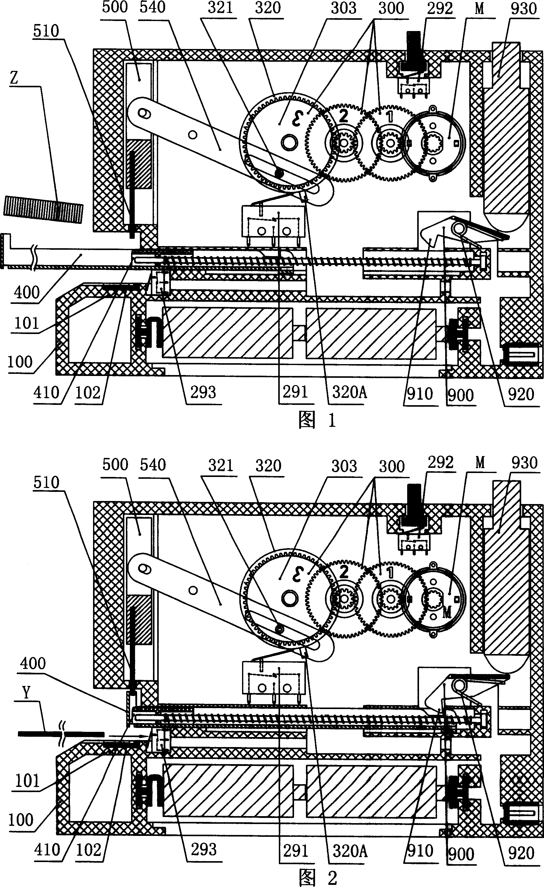
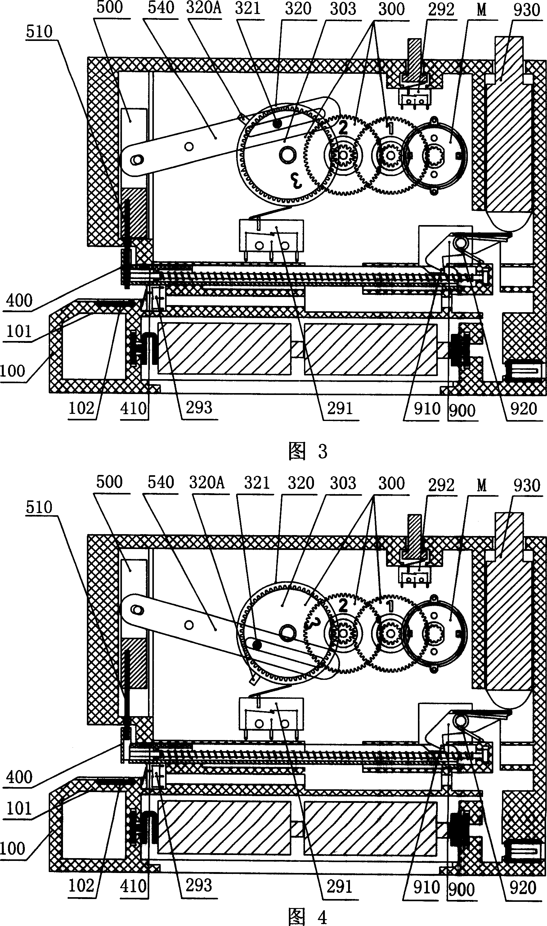
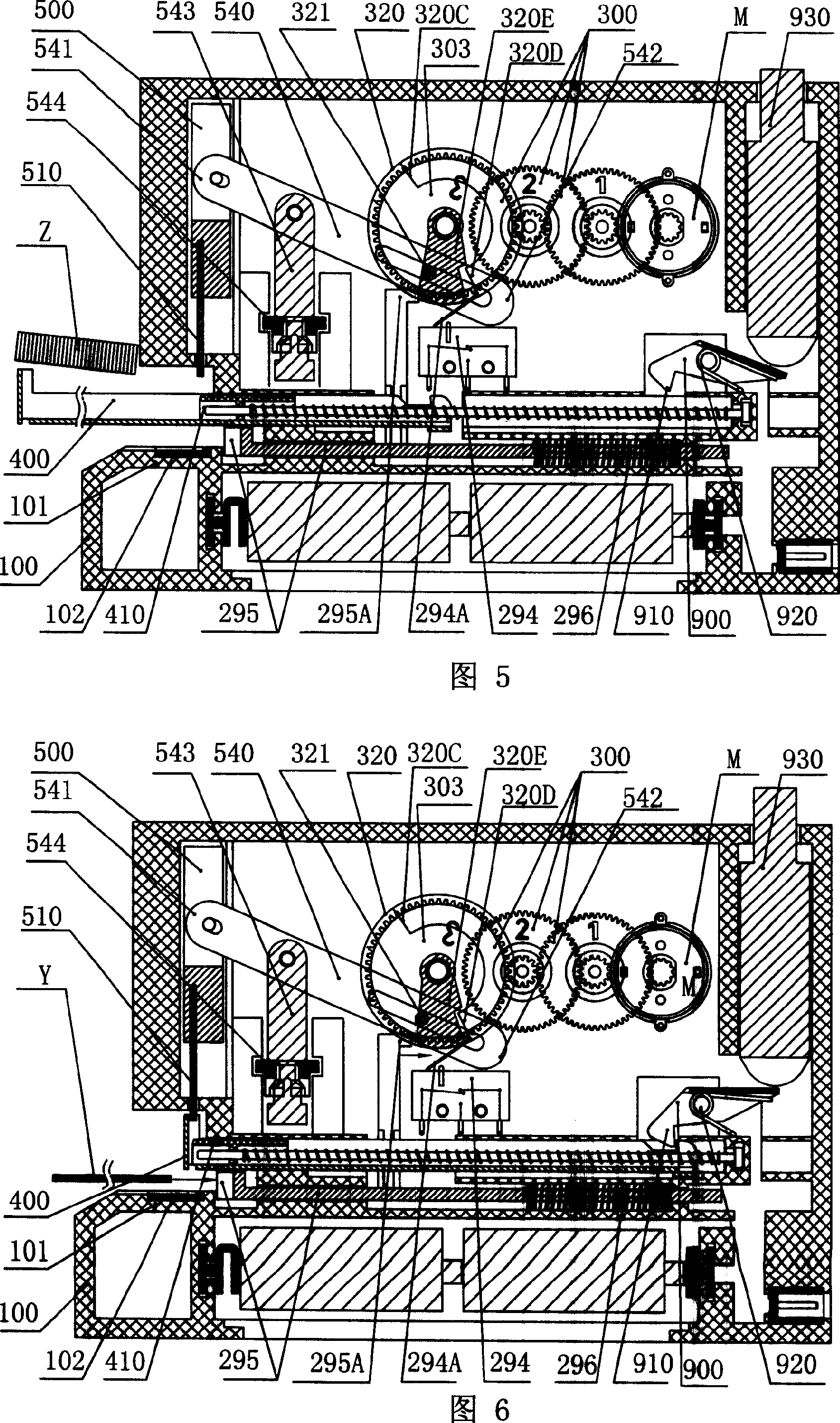
Electric energy storage type stapling machine
A stapler and energy storage technology, which is applied in binding and other directions, can solve the problems of difficult processing size, increased stapler size, and high production cost, and achieves the effects of small power requirements, good stapling effect, and simple structure.
- Summary
- Abstract
- Description
- Claims
- Application Information
AI Technical Summary
Problems solved by technology
Method used
Image
Examples
Embodiment 1
[0041] FIG. 9 is a three-dimensional schematic view of the disassembled structure of Embodiment 1 of the present invention. Embodiment 1 of the energy storage type stapler of the present invention includes a box 100 with a staple holder 101, the box 100 includes a left box and a right box that can be docked and assembled; Straight or curved ribs and compartments for assembling parts are formed on the top, including a battery compartment 130 and an external power socket 131; the box 100 includes a supporting base 120;
[0042] Inside the box 100, a control switch 200 and its circuit, a motor M, a gear set 300 for deceleration and boosting, and a running wheel 320 are installed. In the case 100 , a staple slot 400 and a stapler 500 are vertically slidably fitted with each other, and the stapler 500 and the base 120 are vertically installed in the case 100 . In the book needle groove 400, an elastic needle pusher 410 is slidably fitted, and the stapler 500 is equipped with a sta...
Embodiment 2
[0059] Figures 17-19 are schematic cross-sectional schematic diagrams of the assembly structure at three moments during the operation process of embodiment 2 of the present invention: loading needles out of the trough, feeding paper for delivery, and releasing energy to lift the sheet. Embodiment 2 of the energy storage type stapler of the present invention, except that the following elastic energy storage device 600 and related structures are different from Embodiment 1, the rest of the structures are the same as Embodiment 1:
[0060] The energy storage member includes a torsion spring 610 and an auxiliary lever 614 hinged on respective support shafts 620A, 620B, the outer end of the torsion spring 610 is hooked to the stapler 500, and its middle is hinged by the support shaft 620A Between the two inner sidewalls of the box 100 , the two ends of the auxiliary lever 614 are respectively hinged on the inner end of the torsion spring 610 and the eccentric shaft 321 .
[0061] A...
Embodiment 3
[0065] As shown in Figures 20-25, it shows the assembly of the embodiment 3 of the present invention at six moments during the operation process: loading the needle out of the groove, starting the paper feeding, storing the energy for firing, releasing the energy for pressing the needle, lifting the button, and holding the brake for six moments Schematic diagram of the structural section.
[0066] Embodiment 3 of the energy storage type stapler of the present invention, except that the following elastic energy storage device 600 and related structures are different from Embodiment 1, the rest of the structures are the same as Embodiment 1:
[0067] The energy storage part is a leaf spring 615, the outer end of the leaf spring 615 hooks the nailer 500, the middle part is hinged between the two inner walls of the box 100 through the upper and lower support shafts 621, 622, and its The inner end is bounded in a bounding frame 630 hinged on said eccentric shaft.
[0068] As shown...
PUM
 Abstract
Description
Claims
Application Information
 - R&D
- Intellectual Property
- Life Sciences
- Materials
- Tech Scout
- Unparalleled Data Quality
- Higher Quality Content
- 60% Fewer Hallucinations
Browse by: Latest US Patents, China's latest patents, Technical Efficacy Thesaurus, Application Domain, Technology Topic, Popular Technical Reports.
© 2025 PatSnap. All rights reserved.Legal|Privacy policy|Modern Slavery Act Transparency Statement|Sitemap|About US| Contact US: help@patsnap.com


