

charger
A charger and electrical connection technology, applied in the direction of collectors, electric vehicles, electrical components, etc., can solve the problem of small connection fixing force between chargers and sockets, and achieve small connection fixing force, better fixing effect, and large supporting force. Effect
- Summary
- Abstract
- Description
- Claims
- Application Information
AI Technical Summary
Problems solved by technology
Method used
Image

Examples
Embodiment 1
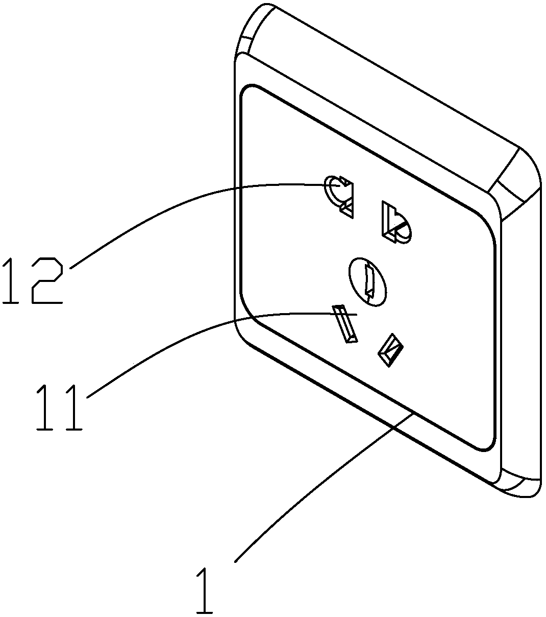
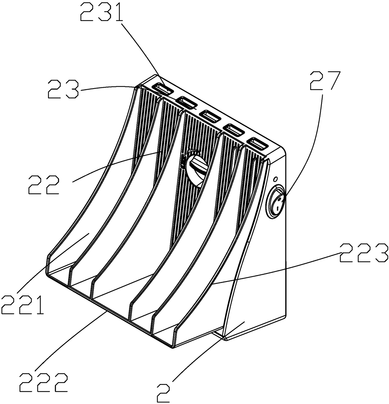
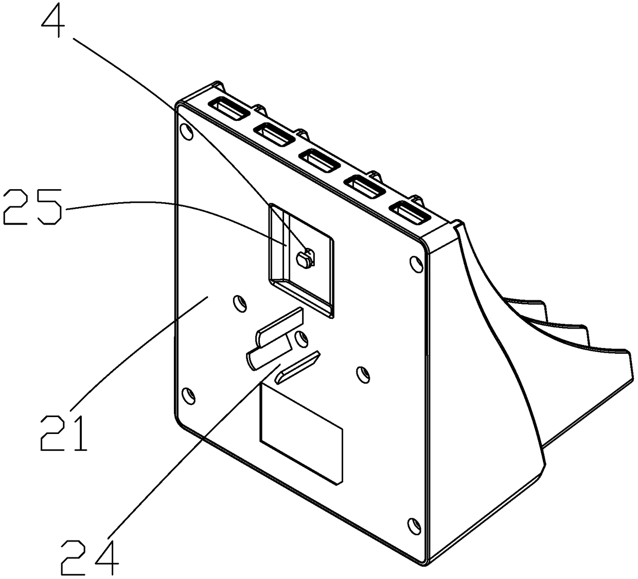
[0031] combine figure 1 , figure 2 and image 3 , the charger body 1 includes a first end face 21, a second end face 22 oppositely disposed, and a third end face 23 connecting the first and second end faces 21, 22; in this embodiment, the first end face 21 is parallel to the second end face Two end faces 22, and the third end face 23 is perpendicular to the first end face 21:
[0032] The first end surface 21 is the end surface facing the socket 1 and in contact with the socket 1, and the first end surface 21 is provided with conductive plugs 24 at a certain distance in the vertical direction. In this embodiment, the conductive plugs 24 It is a triangular plug, including a phase line pin, a neutral line pin and a ground line pin. The phase line pin and the neutral line pin are arranged symmetrically with respect to the ground line pin. The conductive plug part 24 is used to insert into the first jack 11 of the socket 1 Electrically connected, and clamped by the copper shee...
Embodiment 2
[0046] This embodiment is basically the same as Embodiment 1, and its main difference is:
[0047] The second connecting part is a plate made of ferromagnetic material, and the first connecting part is a plastic shell, and a magnet is arranged in the plastic shell.
[0048] The second connecting part is put into the main body and close to the main body, and then the first and second connecting parts are connected by magnetic force.
[0049] It can be understood that, in other embodiments, the connection between the insulating plug part and the body 2 can also be a bolt connection, a dovetail groove structure clamping connection or a snap connection, etc., as long as the insulating plug part is fixed on the first end surface in the vertical direction That is enough; similarly, when the charger only needs to be fixedly matched with a single socket in the actual use needs of customers, the insulated plug part and the body can also be non-detachable connections such as glue bondin...
Embodiment 3
[0051] to combine figure 1 , in this embodiment, the same thing as Embodiment 1 is: the charger includes a body, which is provided with a containing portion for containing electronic products, and a conductive plug portion for electrically connecting with the first socket of the socket, And not less than one output port for electrical connection with the charging terminal of the electronic product.
[0052] This embodiment is different from Embodiment 1 in that: the body is also provided with an insulating plug part, one end of which is integrally connected with the body, and the other end is used to connect with the second jack of the socket, and the insulating plug part is conductive The distance between the plug parts is set according to the distance between the first socket 11 and the second socket 12 on the socket 1 . In use, the body is inserted into the socket 1, correspondingly, the conductive plug part is inserted into the first socket 11 and is clamped by the first ...
PUM
 Abstract
Description
Claims
Application Information