Radio frequency transmitting circuit, bidirectional coupler and directional coupler

A directional coupler and two-way coupling technology, which is applied in transmitter monitoring, electrical components, transmission monitoring, etc., can solve problems such as the complex structure of the two-way coupler, and achieve the effect of simple structure, low insertion loss, and easy integration

Active Publication Date: 2016-07-06
RDA MICROELECTRONICS SHANGHAICO LTD
View PDF12 Cites 21 Cited by
  • Summary
  • Abstract
  • Description
  • Claims
  • Application Information

AI Technical Summary

Benefits of technology

This invention relates to an improved wireless communication system that includes both transmitter circuits for accurate transmission over long distances without sacrificing signal quality or reducing their effectiveness due to changes made during use. It achieves this by providing better control on how much electrical energy needs to be sent through it compared to existing systems while also improving its ability to match different types of signals effectively at longer ranges.

Problems solved by technology

Technologies described include techniques related to reducing electromagnetic interference (EMI) emissions in electronic devices like smartphones due to their proximity to other components located nearby. Current methods involve adding extra parts to reduce EMI but they cannot fully eliminate them altogether because they require different types of materials.

Method used


Image

  • Radio frequency transmitting circuit, bidirectional coupler and directional coupler
  • Radio frequency transmitting circuit, bidirectional coupler and directional coupler
  • Radio frequency transmitting circuit, bidirectional coupler and directional coupler

Examples


Embodiment Construction

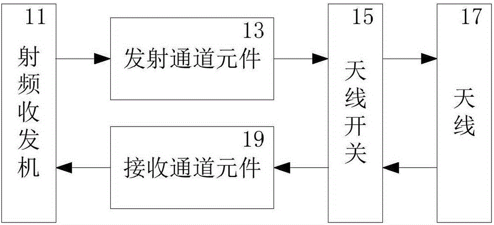
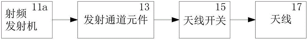
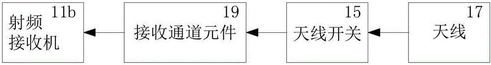
[0049] see Figure 5 , which is a simplified schematic diagram of the RF transceiver circuit of this application, which can be split into Figure 5a The RF transmit circuit of this application is shown and Figure 1b Existing RF receiver circuit shown. The radio frequency transceiver 11 may be replaced by an independent radio frequency transmitter 11 a and a radio frequency receiver 11 b , and the combination of the radio frequency transmitter 11 a and the radio frequency receiver 11 b may also be replaced by the radio frequency transceiver 11 .

[0050] see Figure 5a , the radio frequency transmitting circuit of the present application includes a radio frequency transmitter 11 a , a transmitting channel element 13 , an antenna switch 15 , a bidirectional coupler 21 , an antenna tuner 23 and an antenna 17 . Among them, the transmit channel element 13 includes, for example, a radio frequency power amplifier, a filter, a duplexer, etc., and is mainly used for amplifying and ...


PUM


Abstract

The invention discloses a radio frequency transmitting circuit, comprising a radio frequency transmitter, an antenna switch and an antenna. A bidirectional coupler and an antenna tuner are arranged between the antenna switch and the antenna. The bidirectional coupler comprises a directional coupler and a switch, and forward or reverse transmission power is detected by switching the switch. The directional coupler is provided with a plurality of connected coupling lines, which are respectively located at any one or more positions of the upper side, the lower side, the outer side and the inner side of a main signal line. The bidirectional coupler is both used for detecting the transmitting power and is used for detecting the reflected power and outputting a detection value to the radio frequency transmitter. The radio frequency transmitter is both used for calibrating the transmitting power and is used for adjusting the input impedance of the antenna to realize the impedance matching of the antenna. The invention further discloses a bidirectional coupler, which has the advantages of simple structure, small volume, low cost, and easy integration with the manufacturing process of integrated circuits. The invention further discloses a directional coupler, which has high coupling degree and low insertion loss.

Description


Claims


Application Information

Patent Timeline
Owner RDA MICROELECTRONICS SHANGHAICO LTD
Why Eureka
Try Eureka