
Multi-antenna integrated module

A multi-antenna and antenna technology, applied in the field of multi-antenna integration modules, can solve the problems of difficult control of antenna spacing, easy limitation of the blocking efficiency of antenna isolation, and inability to greatly improve the antenna radiation efficiency.

Active Publication Date: 2012-06-27
昆山展腾电子科技有限公司
View PDF0 Cites 0 Cited by
  • Summary
  • Abstract
  • Description
  • Claims
  • Application Information

AI Technical Summary

Problems solved by technology

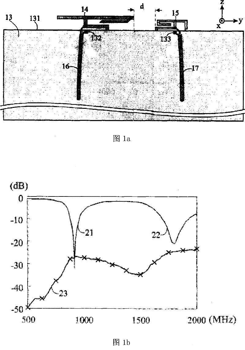
[0004] However, the known first antenna 14 and the second antenna 15 are traditional inverted F-shaped antenna structures. When integrated into the same antenna module, in order to avoid radiation interference effects, the first antenna 14 and the second antenna 15 must be separated by a certain distance. spacing (d), which will increase the overall size of the antenna, and the distance between the antennas is not easy to control, resulting in the antenna radiation efficiency cannot be greatly improved after integration, and the isolation efficiency between different antennas is also easily limited, usually cannot achieve its stated effect

Method used


Image

  • Multi-antenna integrated module
  • Multi-antenna integrated module
  • Multi-antenna integrated module

Examples


Embodiment Construction

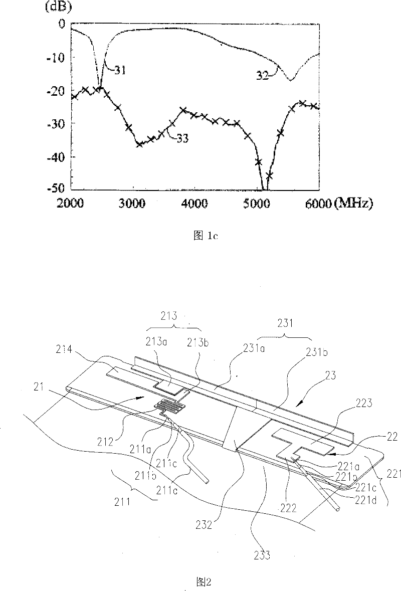
[0023] see figure 2 , is a three-dimensional schematic diagram of the first embodiment of the present invention, the integrated antenna includes: a first antenna 21, a second antenna 22 and a common unit 23; wherein the first antenna 21 includes: a first feeding line 211, a feeding part 212, a coupling unit 213 and an extension conductor 214, the coupling unit 213 also has a first coupling portion 213a and a second coupling portion 213b; the second antenna 22 includes: a second feed line 221, a radiation conductor 222 and a coupling conductor 223; the common unit 23 includes: a combined conductor 231 , a combined short-circuit portion 232 and a combined ground portion 233 , and the combined conductor 231 has a first conductor 231 a and a second conductor 231 b.

[0024] Both the first feeding line 211 and the second feeding line 221 sequentially include central conductors 211a, 221a, inner insulating layers 211b, 221b, outer conductors 211c, 221c, and outer insulating layers ...


PUM


Abstract

The invention relates to a multi-antenna integrated module group, which comprises a first antenna, a second antenna and a common unit, wherein the first antenna is provided with a coupled unit, and the coupled unit is provided with a first coupling portion and a second coupling portion, the second antenna is provided with a coupled conductor, and the common unit is provided with a combined conductor, a combined short-circuit portion and a combined grounding portion. A gap is formed between the other lateral side of the combined conductor of the second conductor, and the connecting interface of the first conductor and the second conductor is connected with an end portion of the combined short-circuit portion, and the other end portion of the combined short-circuit portion is connected withthe combined grounding portion.

Description

technical field [0001] The present invention relates to a multi-antenna integration module, in particular to a multi-antenna integration module with a common unit structure. Background technique [0002] The vigorous development of wireless communication technology has led to the full development of antenna technology, especially in the market for the miniaturization of antenna design and the use of multi-band transmission systems. Therefore, in recent years, various forms of integrated antennas have emerged. structure, integrating different types of antenna structures into the same antenna module, so as to shorten the resonance length of the antenna, thereby reducing the size of the antenna setup. [0003] see Figure 1a , is a schematic plan view of a combined antenna for known dual-network operation, including a ground plane 13 , a first antenna 14 , a second antenna 15 , a first feeding coaxial transmission line 16 and a second feeding coaxial transmission line 17 . The...

Claims


Application Information

Patent Timeline
Patent Type & Authority Patents(China)
IPC IPC(8): H01Q21/28
Inventor 张祐嘉曾义伟邱宗文萧富仁林圣智
Owner 昆山展腾电子科技有限公司
Learn More