Control circuit for universal serial bus control circuit

A universal serial bus and control circuit technology, applied in the direction of electrical digital data processing, instruments, etc., can solve the problems of increasing the circuit area and cost of the control chip, seeing the resistance value not conforming to the C-type USB specification, etc., and saving the circuit area , cost-saving effect

Active Publication Date: 2020-06-16
REALTEK SEMICON CORP
View PDF5 Cites 0 Cited by
  • Summary
  • Abstract
  • Description
  • Claims
  • Application Information

AI Technical Summary

Problems solved by technology

[0003] The control circuit of the conventional Type-C USB independently controls the CC1 pin and the CC2 pin, that is to say, the USB control chip has two pins to respectively control the CC1 pin and the CC2 pin, which increases t

Method used


Image

  • Control circuit for universal serial bus control circuit
  • Control circuit for universal serial bus control circuit
  • Control circuit for universal serial bus control circuit

Examples


Example Embodiment

[0012] The technical terms used in the following description refer to the idioms in the technical field. If some terms are described or defined in this specification, the explanation of the part of terms is based on the description or definition of this specification.

[0013] The disclosure of the present invention includes a USB control circuit. Since some of the components included in the USB control circuit of the present invention may be known components alone, the following description will abbreviate the details of the known components without affecting the full disclosure and implementability of the device invention. .

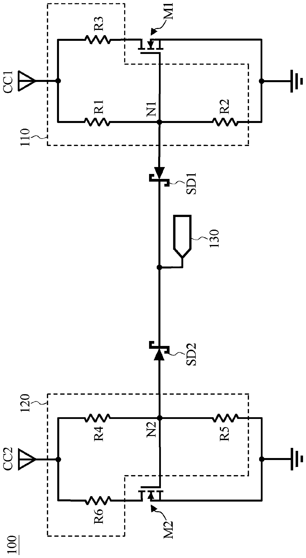
[0014] figure 1 It is a circuit diagram of an embodiment of the USB control circuit of the present invention. The USB control circuit 100 is a part of the USB control chip, and the pin 130 is one of the pins of the USB control chip (also can be regarded as the output / input of the USB control circuit 100). The pin 130 is shared by the CC1 pin and the CC2 p...


PUM


Abstract

The invention discloses a control circuit for a universal serial bus. The universal serial bus comprises a first channel configuration pin and a second channel configuration pin. The control circuit includes: a first transistor having a first control terminal; a first resistor group coupled with a first channel configuration pin and the first transistor; a first Schottky diode is provided with a first end and a second end, wherein the first end is coupled with the first control end; a second transistor provided with a second control end; a second resistor group coupled with the second channelconfiguration pin and the second transistor; and a second Schottky diode provided with a third end and a fourth end, wherein the third end is coupled with the second control end, and the fourth end is coupled with the second end of the first Schottky diode.

Description

technical field [0001] The present invention relates to a universal serial bus (Universal Serial Bus, USB), in particular to a control circuit of the USB. Background technique [0002] Type-C Universal Serial Bus (USB Type-C) has two channel configuration pins: the first channel configuration pin (hereinafter referred to as CC1 pin) and the second channel configuration pin (hereinafter referred to as CC2 pin). ). When a target USB device (such as a host or device) is connected to another USB device (device or host), the target USB device may need to be powered by another USB device (for example, the target USB device is mobile phone, another USB device is a computer), or the target USB device does not need to be powered by another USB device (for example, the target USB device is a monitor, and the other USB device is a mobile phone). According to the USB Type-C specification, for the target USB device to be powered by another USB device, the target USB device without powe...

Claims


Application Information

Patent Timeline
IPC IPC(8): G06F13/40
CPCG06F13/4086G06F2213/0042
Inventor 陈力辅
Owner REALTEK SEMICON CORP
Why Eureka
Try Eureka