Impedance compensation circuit for LED driver and LED driver

A technology of LED driver and impedance compensation, which is applied in the layout of electric lamp circuits, electric light sources, lighting devices, etc., can solve the problems of poor compatibility of thyristors, and achieve the effect of compensating capacitive reactance and improving compatibility.

Active Publication Date: 2017-10-27
MAXIC TECHNOLOGY CORPORATION
View PDF4 Cites 0 Cited by
  • Summary
  • Abstract
  • Description
  • Claims
  • Application Information

AI Technical Summary

Problems solved by technology

[0013] The defect of the prior art is: due to the existence of the EMI capacitor C1, the equivalent input impedance after the rectification bridge is not purely resistive, which will make the compatibility of the LED driver with the thyristor worse, which is reflected in problems such as flashing

Method used


Image

  • Impedance compensation circuit for LED driver and LED driver
  • Impedance compensation circuit for LED driver and LED driver
  • Impedance compensation circuit for LED driver and LED driver

Examples


Embodiment Construction

[0042] In order to make the purpose, technical solutions and advantages of the embodiments of the present invention clearer, the technical solutions in the embodiments of the present invention will be clearly and completely described below in conjunction with the drawings in the embodiments of the present invention. Obviously, the described embodiments It is a part of embodiments of the present invention, but not all embodiments. Based on the embodiments of the present invention, all other embodiments obtained by persons of ordinary skill in the art without making creative efforts belong to the protection scope of the present invention.

[0043] In order to facilitate the understanding of the embodiments of the present invention, the technical solution of the present invention will be further described in detail below with reference to the drawings and embodiments.

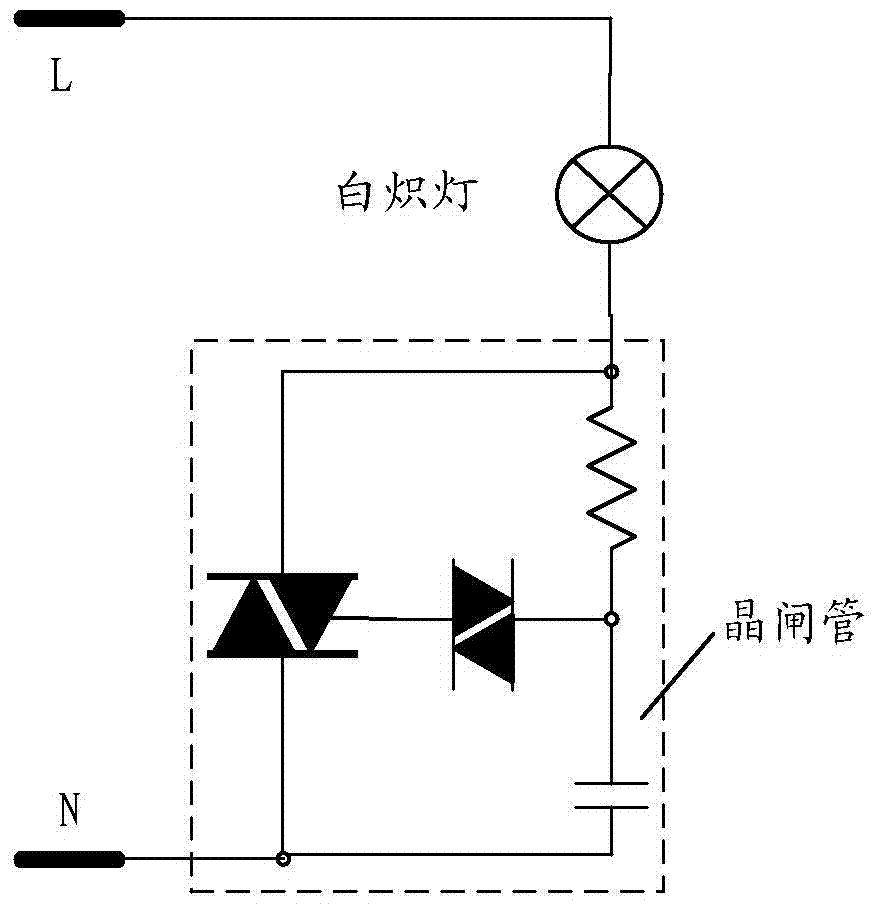
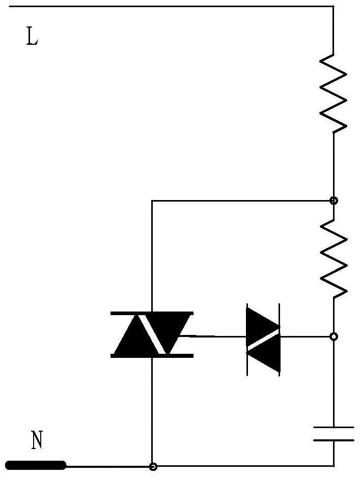
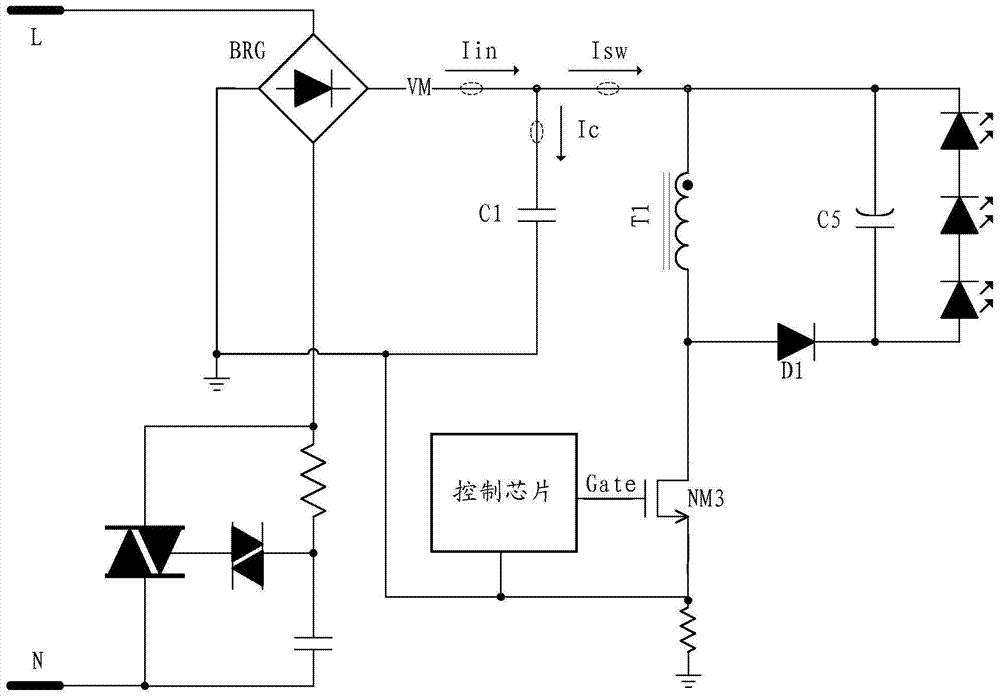
[0044] Figure 6 The schematic diagram of the LED driver circuit provided for the embodiment of the present in...


PUM


Abstract

The invention relates to an LED driver and an impedance compensation circuit used for the same. The impedance compensation circuit comprises a voltage sampler and a time modulator, wherein the voltage sampler is used for sampling voltage of a bus; and the time modulator is used for adjusting equivalent resistance of a switching circuit and compensating capacitive reactance of an EMI capacitor through a control circuit according to the relationship between the sampled bus voltage and a threshold voltage. The LED driver comprises a thyristor, a rectifying circuit, the EMI capacitor, the control circuit, the switching circuit and the impedance compensation circuit, is used for compensating the capacitive reactance of the EMI capacitor, compensating input impedance of the LED driver after passing through the rectifying circuit and the EMI capacitor, and adjusting input current of the LED driver passing through the rectifying circuit. Compared with the prior art, the LED driver provided by the invention can provide sufficient ''holding current'', and has better compatibility for the thyristor.

Description

technical field [0001] The invention relates to the field of lighting driving circuits, in particular to an impedance compensation circuit for an LED driver and the LED driver. Background technique [0002] In traditional lighting (incandescent lighting) circuits, such as figure 1 As shown, the thyristor (Triac) dimming technology is widely used. Its schematic diagram is as follows figure 2 as shown, figure 2 for figure 1 Schematic of the equivalent circuit of the incandescent lighting circuit shown. [0003] Since the equivalent circuit of an incandescent lamp is a resistor, the compatibility of incandescent lamps with thyristors is very good. For LED lighting, its basic circuit is composed of a switching power supply, and since the switching power supply needs to pass the EMI test, a large capacitor needs to be connected in parallel at both ends, such as image 3 shown. [0004] image 3 It is the current LED lighting driving circuit diagram, the control chip can...

Claims


Application Information

Patent Timeline
Patent Type & Authority Patents(China)
IPC IPC(8): H05B37/02
CPCY02B20/40
Inventor 郭越勇刘柳胜程宝洪
Owner MAXIC TECHNOLOGY CORPORATION
Why Eureka
Try Eureka