Wideband antenna

A broadband antenna and wire technology, applied to antennas, loop antennas, resonant antennas, etc., can solve the problems of limited impedance bandwidth, shortening the configuration length of the antenna radiator, and inability to fine-tune the input impedance, so as to shorten the size of the antenna and reduce the configuration space. , the effect of good impedance matching

Inactive Publication Date: 2012-05-23
连展科技电子(昆山)有限公司
View PDF1 Cites 0 Cited by
  • Summary
  • Abstract
  • Description
  • Claims
  • Application Information

AI Technical Summary

Problems solved by technology

The above-mentioned antenna design is to increase the electrical coupling efficiency of the antenna module with a meandering inductance, and can shorten the length of the antenna radiator configuration. However, since the antenna system does not have a multi-stage resonant circuit design, the impedance bandwidth is limited, and the input impedance cannot be fine-tuned. Thereby improving the antenna impedance matching

Method used


Image

  • Wideband antenna
  • Wideband antenna
  • Wideband antenna

Examples


Embodiment Construction

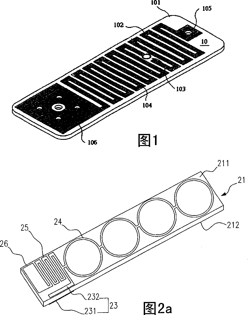
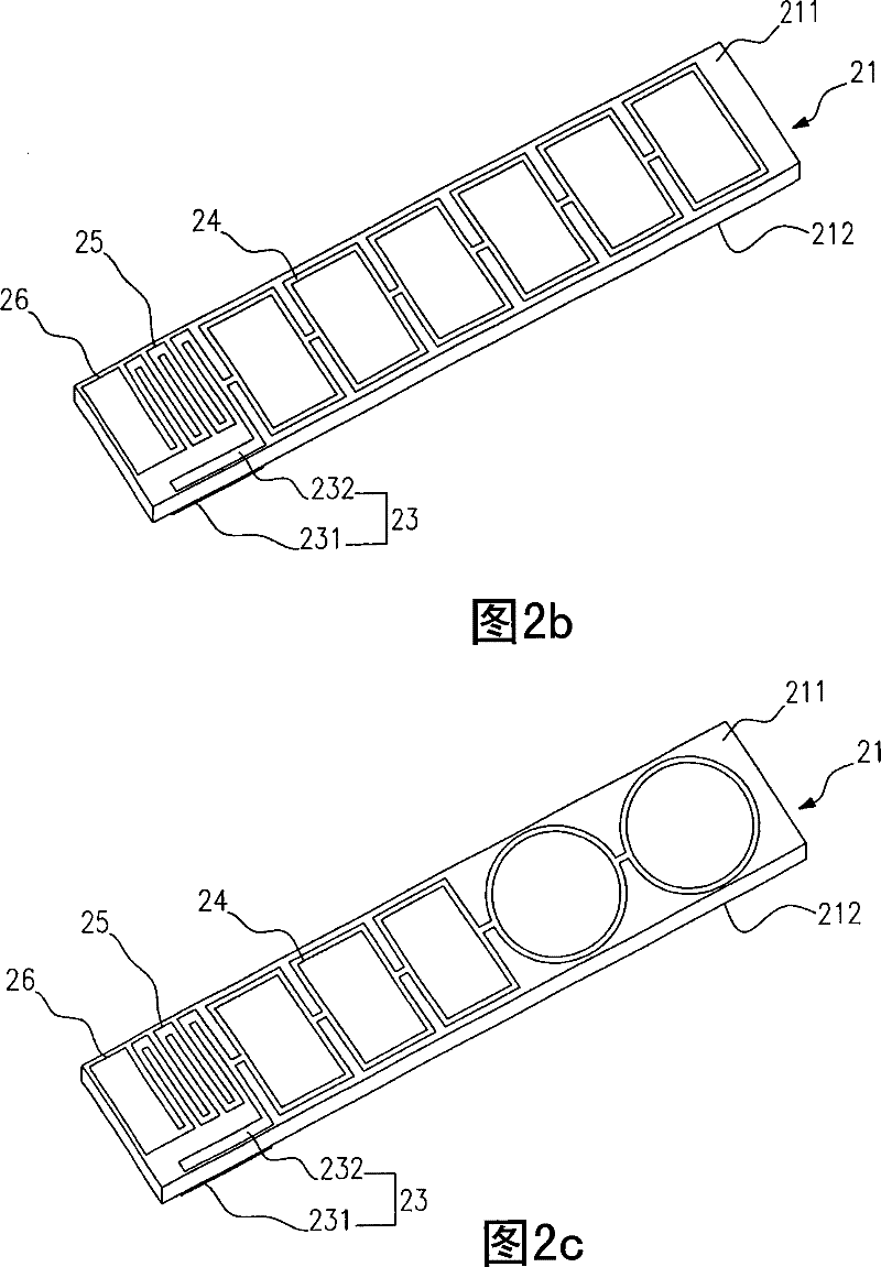
[0019] Figures 2a to 2c It is a three-dimensional schematic diagram of the first embodiment of the present invention, which can have three approximate states, including: a substrate 21, a coupling portion 23, a serial conductor 24, a ground conductor 25, and a ground plane 26; wherein the substrate 21 includes a surface 211 and a bottom surface 212; The coupling portion 23 includes a first coupling portion 231 and a second coupling portion 232 , and the first coupling portion 231 and the second coupling portion 232 are separated by a gap.

[0020] In this embodiment, the first coupling portion 231 is located on the bottom surface 212 of the substrate 21 , and the second coupling portion 232 is located on the surface 211 of the substrate 21 . Since the first coupling portion 231 and the second coupling portion 232 are separated by a gap, the gap is the thickness of the substrate 21 . The substrate 21 has a length of about 109 mm, a width of about 10 mm, and a thickness of abo...


PUM


Abstract

The invention relates to a wideband aerial, comprising a base plate, a coupling part, a serial conductor, a grounding conductor and a ground plane; the coupling part comprises a first coupling part and a second coupling part; the serial conductor is connected with the grounding conductor at the end of the second coupling part; wherein, the serial conductor extends along the direction which is faraway from the second coupling part; the ground plane is connected with the other end of the grounding conductor. In the invention, input impedance is slightly adjusted by the coupling part and the grounding conductor, thus causing the impedance to be matched; a multi-level resonance circuit of the serial conductor is used for improving impedance bandwidth.

Description

technical field [0001] The invention relates to a broadband antenna, in particular to an antenna design with serial conductors. Background technique [0002] With the diversification of functions of wireless communication equipment and consumer electronic products, the requirements for antenna design are becoming more and more stringent. On the one hand, it must match the product shape design and take into account the good reception effect; on the other hand, it must meet the electromagnetic wave requirements of various wireless communication technologies. characteristics, so that the antenna technology continues to move towards the direction of broadband and miniaturization. In order to pursue the aesthetic appearance of end products, developing smaller-sized antennas has become an important issue for manufacturers in product development. The monopole antenna is produced under this market trend, which removes the negative radiator of the dipole antenna and replaces it with...

Claims


Application Information

Patent Timeline
Patent Type & Authority Patents(China)
IPC IPC(8): H01Q1/38H01Q7/00H01Q9/30
Inventor 陈文祥张耀元萧智仁邱宗文萧富仁
Owner 连展科技电子(昆山)有限公司
Why Eureka
Try Eureka