Coupled aerial

A technology for coupling antennas and coupling units, which is applied to antennas, antenna arrays, resonant antennas, etc., can solve the problems of increasing the overall thickness of the antenna, reducing the overall volume, and increasing the difficulty of manufacturing, and achieves reduced antenna size, good radiation efficiency, and smooth impedance. effect of change

Active Publication Date: 2010-12-29
昆山展腾电子科技有限公司
View PDF2 Cites 1 Cited by
  • Summary
  • Abstract
  • Description
  • Claims
  • Application Information

AI Technical Summary

Problems solved by technology

[0004] Although the above design can achieve the purpose of multi-frequency operation, since the radiating arm 150 and the radiating arm 170 are bent in a Z-shaped symmetrical structure to increase the bandwidth, although this method can shorten the length of the antenna, it also leads to an increase in the overall thickness of the antenna, and The ground plane GPN, ground point G, short-circuit component ST and short-circuit regulator REG must also be bent to reduce the overall volume. Do not install the short-circuit regulator REG, the overall structure of the antenna is too complicated, and the operating bandwidth of the antenna has a certain upper limit, which cannot really achieve the effect of broadband

Method used


Image

  • Coupled aerial
  • Coupled aerial
  • Coupled aerial

Examples


Embodiment Construction

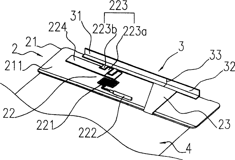
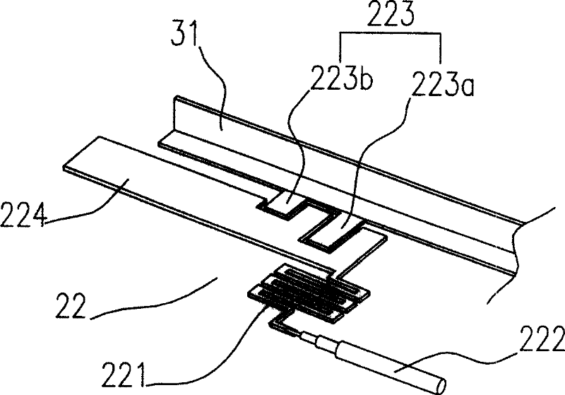
[0020] see figure 2 , is a three-dimensional assembly diagram of the first embodiment of the present invention, including a main radiator 2 , a secondary radiator 3 and a ground plane 4 . The main radiator 2 includes a substrate 21, a feeding coupling unit 22 located on the surface 211 of the substrate 21, and a short circuit portion 23, and the feeding coupling unit 22 includes a feeding portion 221, a feeding line 222, a coupling part 223 and an extension conductor 224 ; the secondary radiator 3 is connected to the substrate 21 of the main radiator 2 and includes a first conductor 31 and a second conductor 32 .

[0021] The substrate 21 of the main radiator 2 has a length of about 84 mm and a width of about 9 mm. The feed-in portion 221 of the feed-in coupling unit 22 is set in a meandering shape with a total path length of about 8mm, which is used to generate an inductive effect; the feed-in line 222 is connected to one end of the feed-in portion 221, and the high-frequen...


PUM


Abstract

The invention provides a coupling antenna, which includes: a main radiator, an assistant radiator and a ground surface. The main radiator includes: a substrate, a feed-in coupling unit and a short circuit part, the assistant radiator includes: a first conductor and a second conductor, therein, the feed-in coupling unit includes: a feed-in part, a feed-in wire, a coupling part and an extension conductor; the assistant radiator is connected with the main radiator substrate, resonant frequency of antenna resonant mode is adjusted by using the extension conductor, the first conductor and the second conductor, and electric coupling effect is produced by the feed-in coupling unit, radiation signal transmission efficiency is increased, antenna system operation frequency width is increased.

Description

technical field [0001] The invention relates to a coupling antenna, in particular to a broadband coupling antenna with increased multi-frequency resonance mode operation. Background technique [0002] With the advancement of wireless communication transmission technology, the functions of information products have become more and more advanced. The equipment has changed from wired Internet access to wireless Internet access, and now it has progressed to the integrated application of multi-band wireless transmission. The most critical component affecting transmission efficiency is the antenna. , How to increase the operating bandwidth of the antenna and improve the application range of the frequency band, and at the same time achieve the purpose of miniaturizing the overall size of the antenna, has become a subject for the relevant industry to actively seek improvement. [0003] Different regions use different communication standards and use different transmission frequency b...

Claims


Application Information

Patent Timeline
Patent Type & Authority Patents(China)
IPC IPC(8): H01Q5/00H01Q21/00H01Q9/30H01Q5/10H01Q5/28H01Q5/364H01Q5/378H01Q5/50
Inventor 林圣智曾义伟邱宗文萧富仁
Owner 昆山展腾电子科技有限公司
Why Eureka
Try Eureka