Data storage system having point-to-point configuration

a data storage system and point-to-point configuration technology, applied in the field of data storage systems, can solve the problem of increasing the data transfer bandwidth of the system, and achieve the effect of facilitating data transfer

Inactive Publication Date: 2006-02-28
EMC IP HLDG CO LLC
View PDF90 Cites 10 Cited by
  • Summary
  • Abstract
  • Description
  • Claims
  • Application Information

AI Technical Summary

Benefits of technology

[0016]In accordance with the present invention, a system interface is provided. Such interface includes a plurality of first directors, a plurality of second directors, a data transfer section and a message network. The data transfer section includes a cache memory. The cache memory is coupled to the plurality of first and second directors. The messaging network operates independently of the data transfer section and such network is coupled to the plurality of first directors and the plurality of second directors. The first and second directors control data transfer between the first directors and the second directors in response to messages passing between the first directors and the second directors through the messaging network to facilitate data transfer between first directors and the second directors. The data passes through the cache memory in the data transfer section.
[0017]With such an arrangement, the cache memory in the data transfer section is not burdened with the task of transferring the director messaging but rather a messaging network is provided, operative independent of the data transfer section, for such messaging thereby increasing the operating bandwidth of the system interface.

Problems solved by technology

Further, the use of two buses increases the data transfer bandwidth of the system compared to a system having a single bus.

Method used


Image

  • Data storage system having point-to-point configuration
  • Data storage system having point-to-point configuration
  • Data storage system having point-to-point configuration

Examples


Embodiment Construction

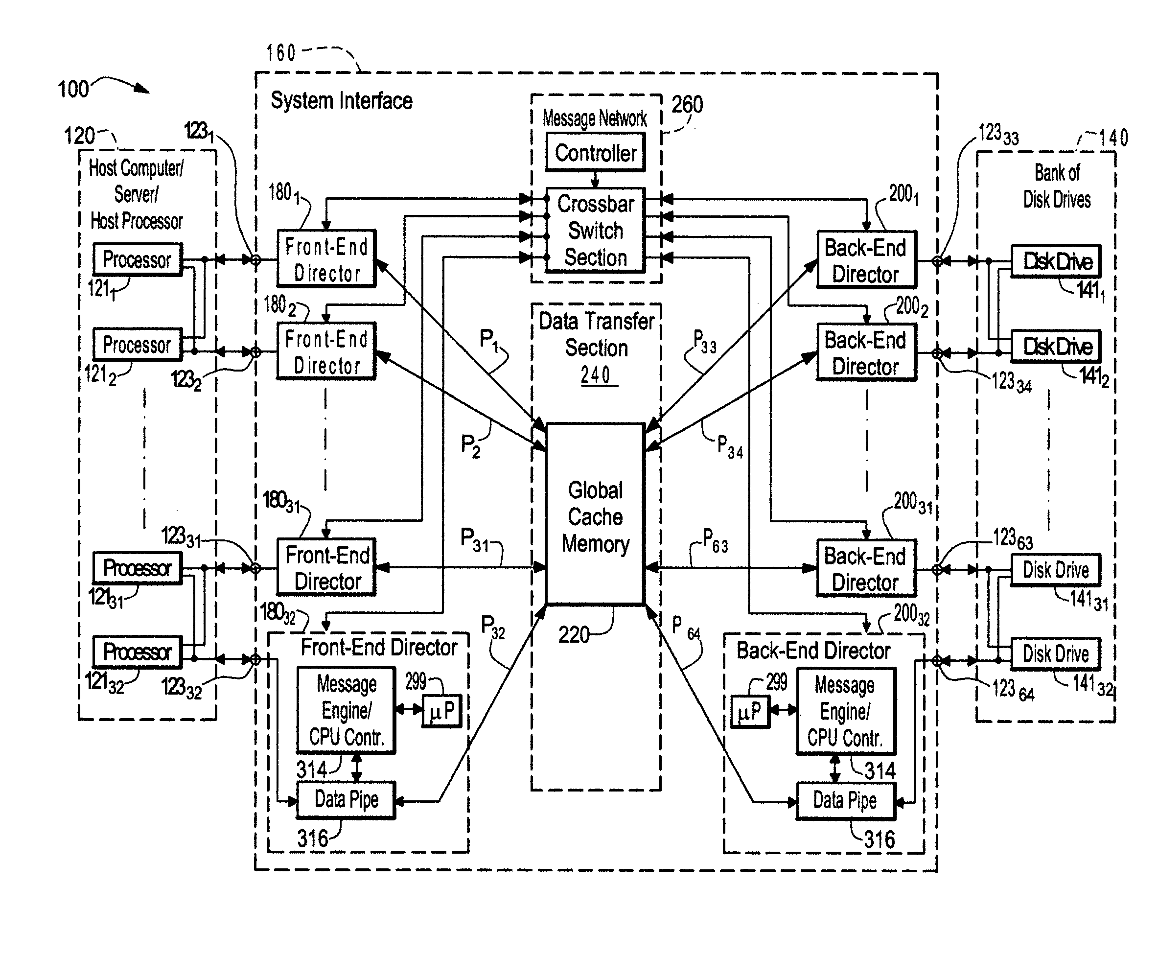
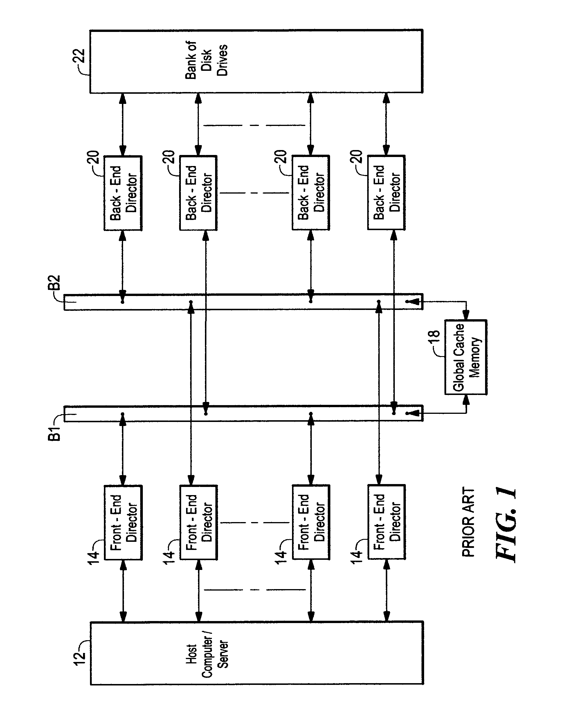
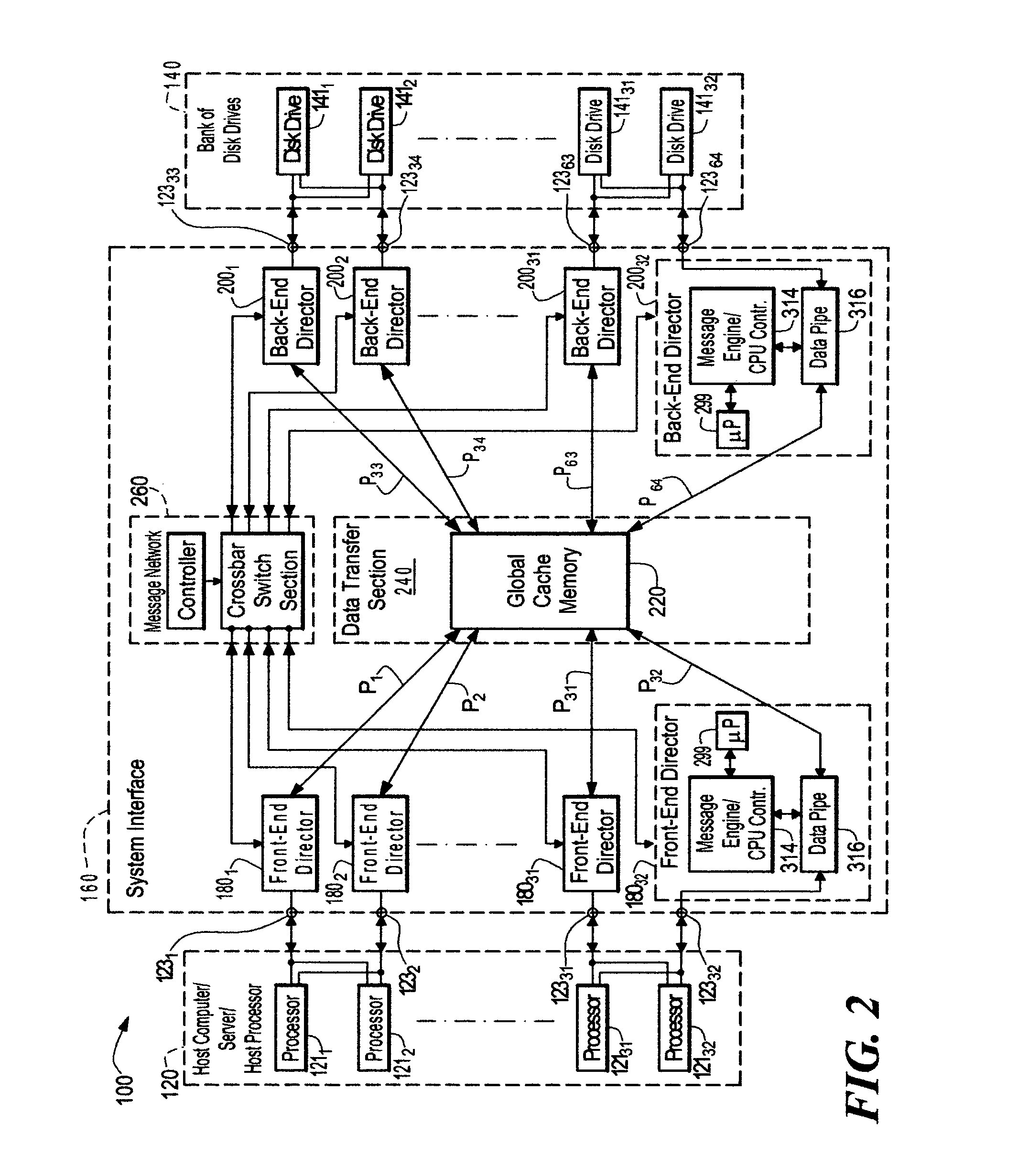
[0046]Referring now to FIG. 2, a data storage system 100 is shown for transferring data between a host computer / server 120 and a bank of disk drives 140 through a system interface 160. The system interface 160 includes: a plurality of, here 32 front-end directors 1801–18032 coupled to the host computer / server 120 via ports-12332; a plurality of back-end directors 2001–20032 coupled to the bank of disk drives 140 via ports 12333–12364; a data transfer section 240, having a global cache memory 220, coupled to the plurality of front-end directors 1801–18016 and the back-end directors 2001–20016; and a messaging network 260, operative independently of the data transfer section 240, coupled to the plurality of front-end directors 1801–18032 and the plurality of back-end directors 2001–20032, as shown. The front-end and back-end directors 1801–18032, 2001–20032 are functionally similar and include a microprocessor (μP) 299 (i.e., a central processing unit (CPU) and RAM), a message engine / ...


PUM


Abstract

A system interface includes a plurality of first directors, a plurality of second directors, a data transfer section and a message network. The data transfer section includes a cache memory. The cache memory is coupled to the plurality of first and second directors. The messaging network operates independently of the data transfer section and such network is coupled to the plurality of first directors and the plurality of second directors. The first and second directors control data transfer between the first directors and the second directors in response to messages passing between the first directors and the second directors through the messaging network to facilitate data transfer between first directors and the second directors. The data passes through the cache memory in the data transfer section. A method for operating a data storage system adapted to transfer data between a host computer / server and a bank of disk drives. The method includes transferring messages through a messaging network with the data being transferred between the host computer / server and the bank of disk drives through a cache memory, such message network being independent of the cache memory.

Description

CROSS REFERENCE TO RELATED APPLICATIONS[0001]This application claims the benefit of the filing dates of the following co-pending patent applications under the provisions of 35 U.S.C. §120:[0002]Ser. No. 09 / 540,828, entitled “Data Storage System Having Separate Data Transfer Section And Message Network”, inventors Yuval Ofek, David L. Black, Stephen D. MacArthur, Richard Wheeler and Robert Thibault, filed Mar. 31, 2000;[0003]Ser. No. 09 / 540,825, entitled “Data Storage System Having Separate Data Transfer Section And Message Network With Plural Directors On A Common Printed Circuit Board And Redundant Switching Networks”, inventors David L. Black, Richard Wheeler, Robert Thibault, Stephen D. MacArthur and Yuval Ofek, filed Mar. 31, 2000;[0004]Ser. No. 09 / 539,966, entitled “Data Storage System Having Separate Data Transfer Section And Message Network With Plural Directors On A Common Printed Circuit Board”, inventor Stephen D. MacArthur, filed Mar. 31, 2000;[0005]Ser. No. 09 / 540,827, e...

Claims


Application Information

Patent Timeline
Patent Type & Authority Patents(United States)
IPC IPC(8): G06F11/00
CPCG06F11/201G06F12/0866G06F11/2089G06F2201/85
Inventor WILSON, PAUL C.ZANI, MARKKHAN, FAROUKMACLELLAN, CHRISTOPHER S.WALTON, JOHN K.MACARTHUR, STEVENCHILTON, KENDALL A.TUCCIO, WILLIAMTHIBAULT, ROBERT A.
Owner EMC IP HLDG CO LLC
Why Eureka
Try Eureka