
Device and method for transmission in a switch

a switch and switch technology, applied in data switching networks, data switching details, multiplex communication, etc., can solve the problems of inability to carry out efficient switching in all circumstances, complex and costly crossbar-based solutions exist, and cannot be used to achieve efficient switching, etc., to achieve the effect of simplifying the implementation of the device and reducing its cos

Inactive Publication Date: 2002-09-12
CANON KK
View PDF8 Cites 47 Cited by
  • Summary
  • Abstract
  • Description
  • Claims
  • Application Information

AI Technical Summary

Benefits of technology

[0058] Furthermore, the invention can advantageously be used to avoid the problems of congestion within receiver ports while optimizing the total data bit rate.
[0065] Thus, the invention advantageously enables a simple and flexible implementation of the method to optimize data transmission especially in multicast mode (by the duplication of data over several rows of the switching matrix).
[0084] Thus, the number of connection buses between the interfacing means and other means is advantageously limited. This simplifies the implementation of the device and / or reduces its cost.

Problems solved by technology

Besides, the packet switching technique does not allow for efficient multicast transmission (namely transmission from one source port to at least two target ports) except if costly and complicated switching matrixes known as > are implemented.
Crossbar-based solutions exist but they remain complex and costly.
A first drawback of the prior art is that it cannot be used to carry out efficient switching in all circumstances, in optimizing the performance characteristics (par example, the bit rate for each communication or the total bit rate).
Another drawback is the fact that the prior art techniques using the "store and foreword routing" architecture have a high degree of latency and require greater memory capacity.

Method used


Image

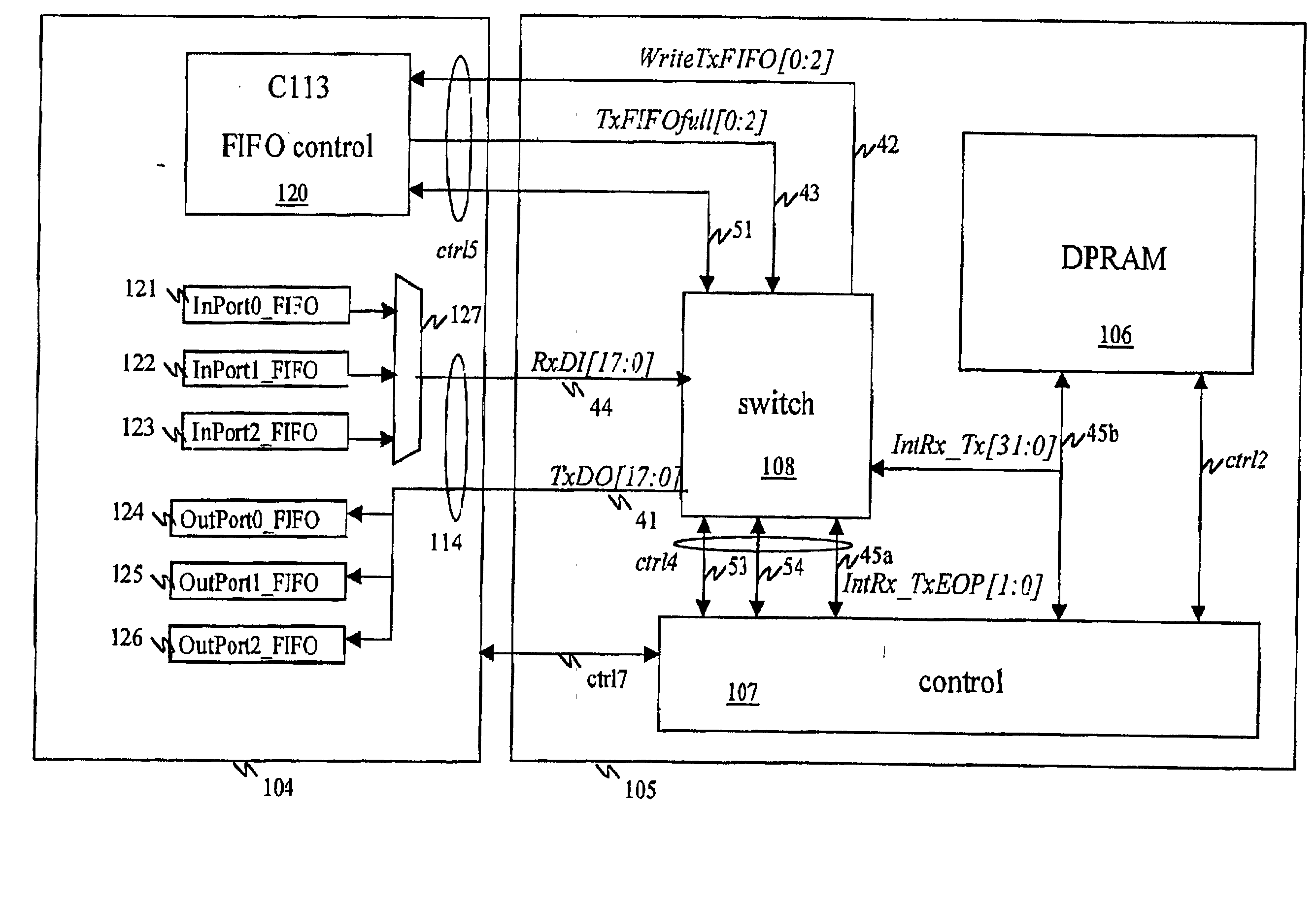
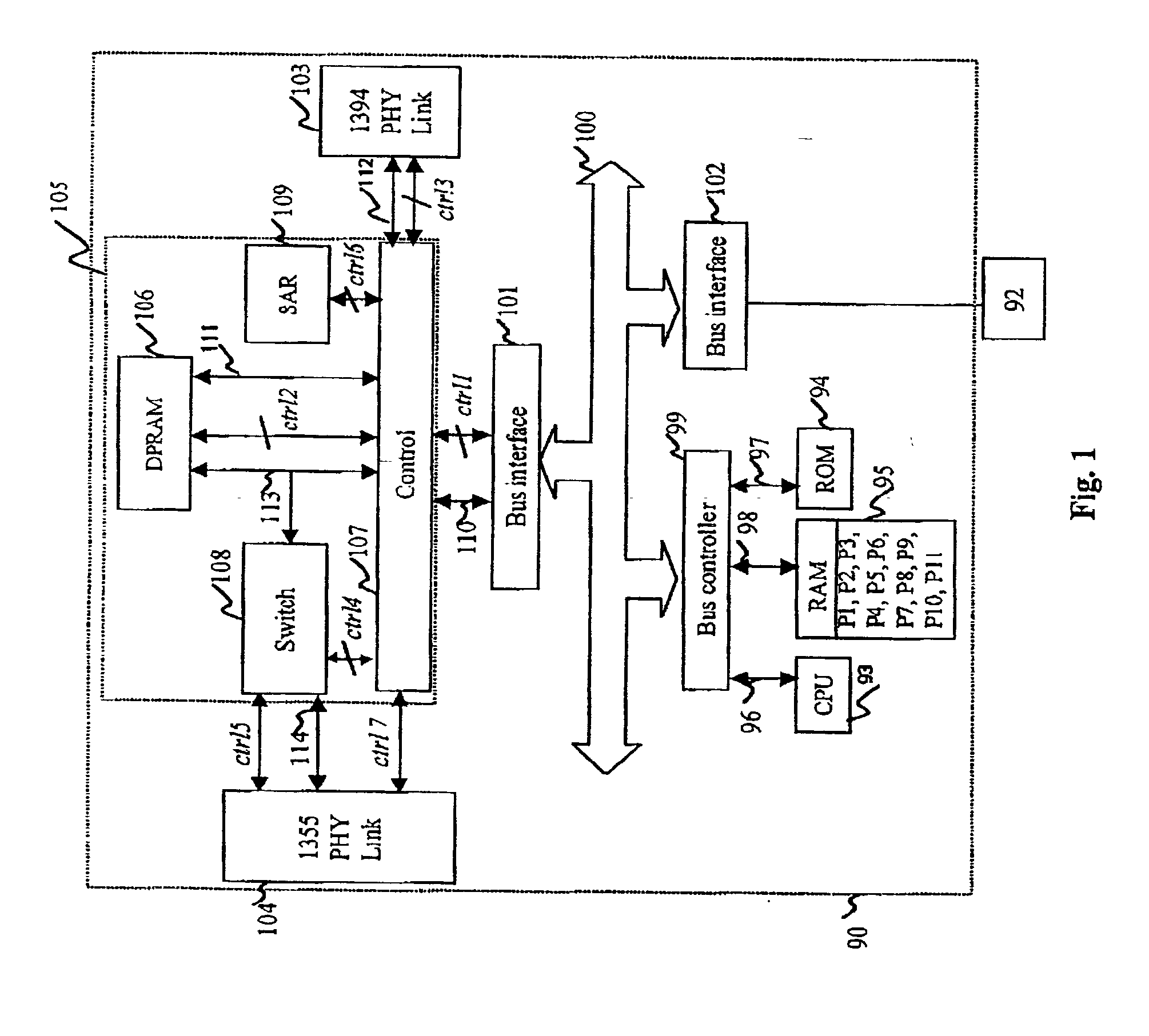
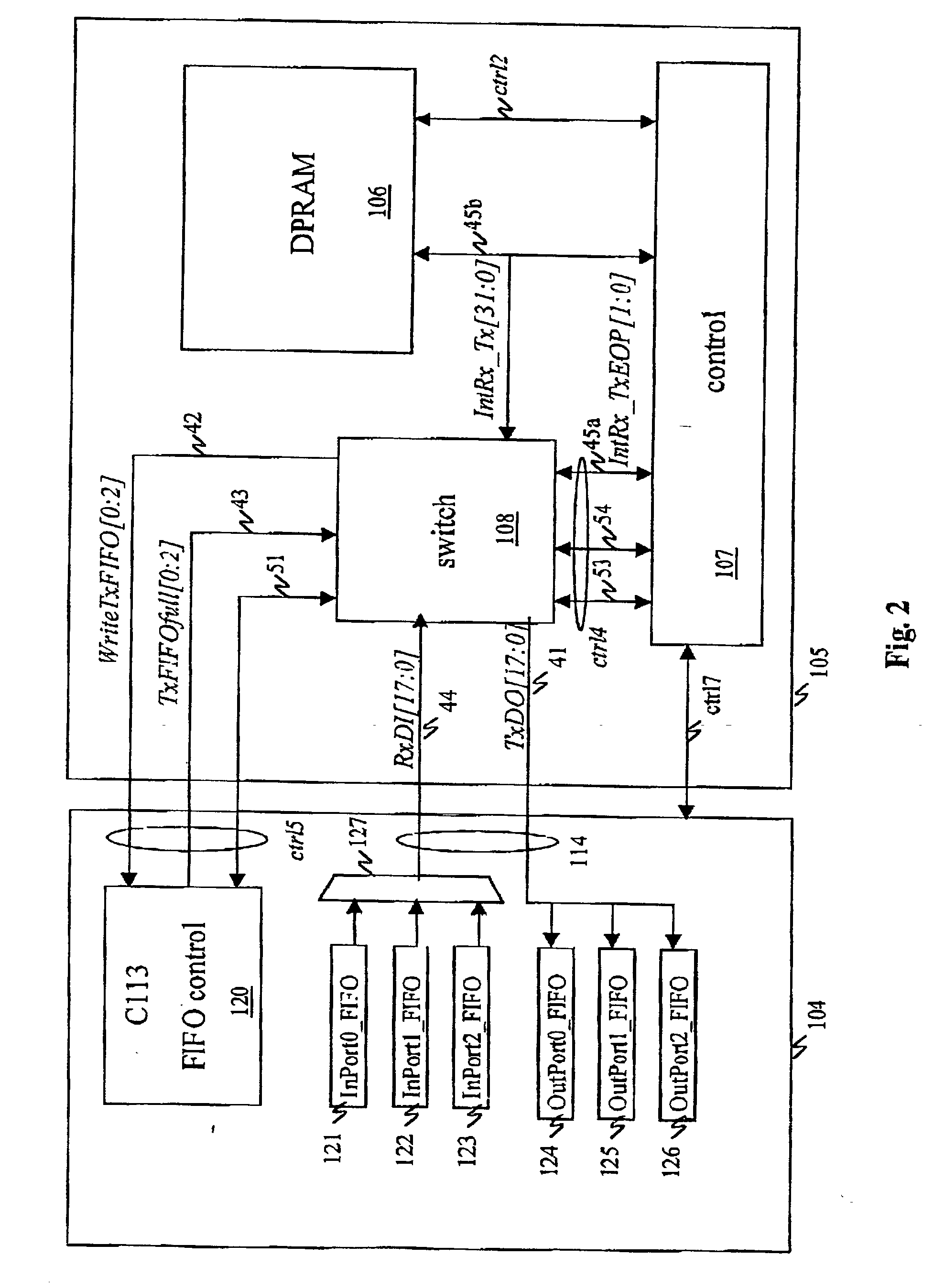
  • Device and method for transmission in a switch
  • Device and method for transmission in a switch
  • Device and method for transmission in a switch

Examples


Embodiment Construction

[0119] The invention can be applied in many fields, and can be applied especially in the context of:

[0120] high bit rate switching;

[0121] distributed applications;

[0122] the transmission and / or reception of digital data;

[0123] audio applications;

[0124] company networks, and

[0125] real-time image transmission.

[0126] A preferred field of application of the invention is that of domestic applications for high bit rate transfers. Here below, we shall describe an exemplary system implementing the invention, used to interconnect a plurality of audio and video devices in a dwelling.

[0127] The standards IEEE 1394 and the IEEE 1355 are respectively adapted to serial communications and to unicast communications.

[0128] The system presented here below in the document is a switched bit rate federating network used to achieve high transmission capacities (typically in the range of one Gbit) and meeting the major requirement of interfacing of the two types of standards referred to here above.

[0129]...


PUM


Abstract

A protocol data unit switching implements switching means used for the selective interconnection of a transmitter port and at least one receiver port selected from among at least two receiver ports by means of at least one internal bus, each of the protocol data units being constituted by at least one piece of elementary data. The switching implements a synchronization mechanism defining time slots, known as connection cycles, on at least one of said internal buses; a mechanism for the allocation of at least one of said connection cycles to each of the selected receiver ports; and a mechanism for the writing of at least one piece of elementary data in the allocated connection cycle or cycles so as to enable the broadcasting of elementary data to said selected receiver ports.

Description

BACKGROUND OF THE INVENTION[0001] 1. Field of the Invention[0002] The present invention pertains to the field of switched networks and, especially, to data transmission in a switched network at high bit rates.[0003] It may be recalled that switching enables the accurate routing of data between a source and one or more destinations, these data being organized in protocol data units and, for example, in packets.[0004] 2. Description of the Prior Art[0005] In the prior art, two different switching techniques are known:[0006] circuit switching; and[0007] packet switching.[0008] A circuit switched network interconnecting several devices essentially uses Time Division Multiplexing or TDM. This technique enables synchronous data transmission by the allocation of time slots on the TDM bus to a variety of synchronous communications. At input, a source apparatus writes data on one or more time slots allocated to it. At output, one or more target apparatuses read the data in the time slot to w...

Claims


Application Information

Patent Timeline
IPC IPC(8): H04L12/18H04L12/46H04L49/111
CPCH04L12/1886H04L12/46H04L45/40H04L49/102H04L49/201H04L49/254H04L49/30H04L49/351
Inventor FROUIN, LAURANTCLOSSET, ARNAUDTANNHAUSER, FALK
Owner CANON KK
Learn More