Sprinkler and unmanned aerial vehicle comprising same

A technology of spraying device and crankshaft, applied in the field of spraying device and unmanned aerial vehicle, can solve the problems of difficulty in atomizing turntable, splashing of droplets, easy splashing of droplets, etc., and achieves improved spraying uniformity, exquisite overall structure, and improved spraying. performance effect

Active Publication Date: 2016-07-13
GUANGZHOU XAIRCRAFT TECH CO LTD
View PDF6 Cites 17 Cited by
  • Summary
  • Abstract
  • Description
  • Claims
  • Application Information

AI Technical Summary

Problems solved by technology

Specifically, when the pesticide pouring port is set at the edge of the atomizing turntable, the atomizing turntable is prone to splashing droplets during the spraying process, and it is difficult to spray evenly on the circumference; when the pesticide pouring port is set at the edge of the atomizing turntable In the central part, the shaft of the motor needs to be hollow designed so that the pesticide can be injected into the atomizing turntable from the central hole on the shaft. The pesticide spraying device with this design not only has a complex structure, poor reliability, but also high cost
[0003] In addition, the top of the atomizing turntable in the related art is usually in an open state, so that the sprayed liquid droplets are easily splashed on the motor, causing corrosion of the motor. When the atomization turntable is not set horizontally, it is difficult for the liquid on the atomization turntable to spread evenly within the entire circumference of the atomization turntable, making it difficult for the atomization turntable to spray evenly in the entire circumferential direction

Method used


Image

  • Sprinkler and unmanned aerial vehicle comprising same
  • Sprinkler and unmanned aerial vehicle comprising same
  • Sprinkler and unmanned aerial vehicle comprising same

Examples


Embodiment Construction

[0049] Embodiments of the present invention are described in detail below, examples of which are shown in the drawings, wherein the same or similar reference numerals designate the same or similar elements or elements having the same or similar functions throughout. The embodiments described below by referring to the figures are exemplary and are intended to explain the present invention and should not be construed as limiting the present invention.

[0050] The following disclosure provides many different embodiments or examples for implementing different structures of the present invention. To simplify the disclosure of the present invention, components and arrangements of specific examples are described below. Of course, they are only examples and are not intended to limit the invention. Furthermore, the present invention may repeat reference numerals and / or letters in different instances. This repetition is for the purpose of simplicity and clarity and does not in itself...


PUM


Abstract

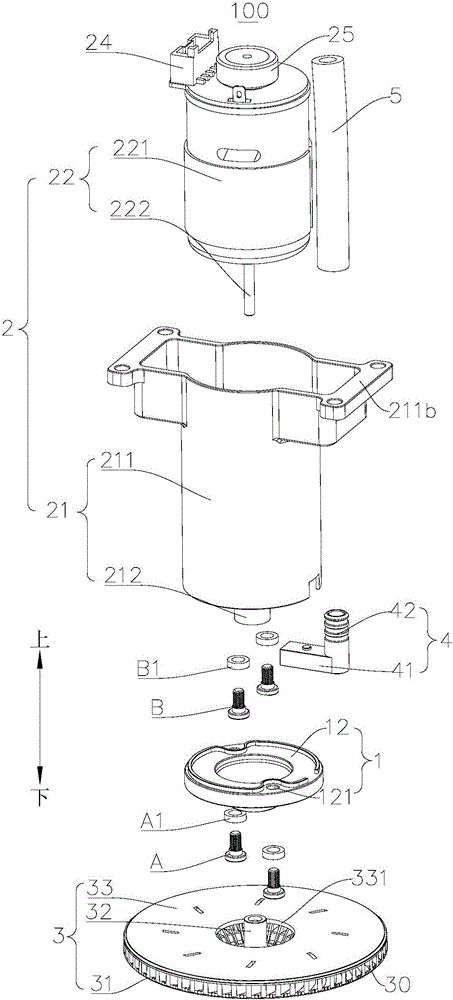
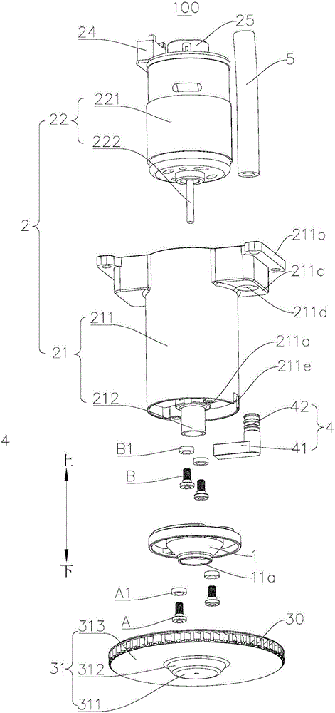
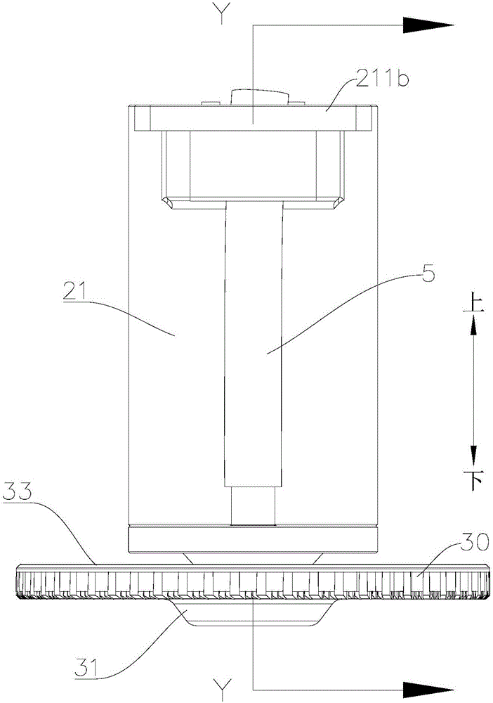
The invention discloses a sprinkler and an unmanned aerial vehicle comprising the same. The sprinkler comprises a liquid hopper, a motor and a centrifugal sprinkling disk, wherein a liquid drain outlet is formed in the bottom of the liquid hopper; the motor comprises a core and a shaft, the core is arranged above the liquid hopper, and the shaft is connected with the core and extends downwards into the liquid hopper from the top of the liquid hopper; the centrifugal sprinkling disk comprises a rotating disk and a rotating shaft, the rotating disk is positioned below the liquid hopper to receive liquid drained from the liquid drain outlet, and the rotating shaft is fixed in the center of the rotating disk and extends upwards into the liquid hopper from the liquid drain outlet to be connected with the shaft directly. The sprinkler has the advantages that since the liquid drain outlet sleeves the rotating shaft, the liquid hopper can pour liquid towards the center of the centrifugal sprinkling disk to increase sprinkling uniformity and improve droplet splashing effectively; since the liquid is poured to the centrifugal sprinkling disk by the liquid hopper, machining the shaft to be of a hollow structure is unneeded, and machining difficulty and production cost are lowered accordingly.

Description

technical field [0001] The invention relates to the technical field of spraying, in particular to a spraying device and an unmanned aerial vehicle equipped with the same. Background technique [0002] In the pesticide spraying device for unmanned aerial vehicles in the related art, the pesticide pouring port is usually set at the center or edge of the atomization turntable. Specifically, when the pesticide pouring port is set at the edge of the atomizing turntable, the atomizing turntable is prone to splashing droplets during the spraying process, and it is difficult to spray evenly on the circumference; when the pesticide pouring port is set at the edge of the atomizing turntable In the central part, the shaft of the motor needs to be designed hollow so that the pesticide can be injected into the atomizing turntable from the center hole on the shaft. The pesticide spraying device with this design not only has complex structure, poor reliability, but also high cost. [0003...

Claims


Application Information

Patent Timeline
Patent Type & Authority Applications(China)
IPC IPC(8): B05B3/08B05B13/02B64D1/18
CPCB64D1/18B05B3/082B05B13/0278B64U2101/00
Inventor 何建兵肖锭锋
Owner GUANGZHOU XAIRCRAFT TECH CO LTD
Why Eureka
Try Eureka