
Demolition pliers

A demolition and plier handle technology, applied in the field of demolition pliers, can solve the problems of inconvenient operation by a single person, the overall weight of the pliers body, and the difficulty of demolition, etc., to reduce the probability of damage, simple and reliable structure, good breaking dismantling effect

Active Publication Date: 2018-03-23
张诗贺
View PDF7 Cites 0 Cited by
  • Summary
  • Abstract
  • Description
  • Claims
  • Application Information

AI Technical Summary

Problems solved by technology

[0002] At present, the fire-fighting special hydraulic rescue pliers have good demolition and cutting capabilities, but the structure is complex and the overall weight of the pliers is large, and it is inconvenient for a single person to operate, which is not conducive to popularization and is expensive.
And the hydraulic rescue pliers in the prior art are generally straight-line shearing blades, the structure of the above-mentioned rescue pliers is relatively simple, and there are the following disadvantages in use: (1) a larger active force must be applied when in use It is more laborious to form a cut; (2) the cutting edge is easy to passivate after a period of use, which further increases the difficulty of demolition

Method used


Image

  • Demolition pliers
  • Demolition pliers
  • Demolition pliers

Examples


Embodiment Construction

[0028] It should be noted that, in the case of no conflict, the embodiments of the present invention and the features in the embodiments can be combined with each other.

[0029] The present invention will be described in detail below with reference to the accompanying drawings and examples.

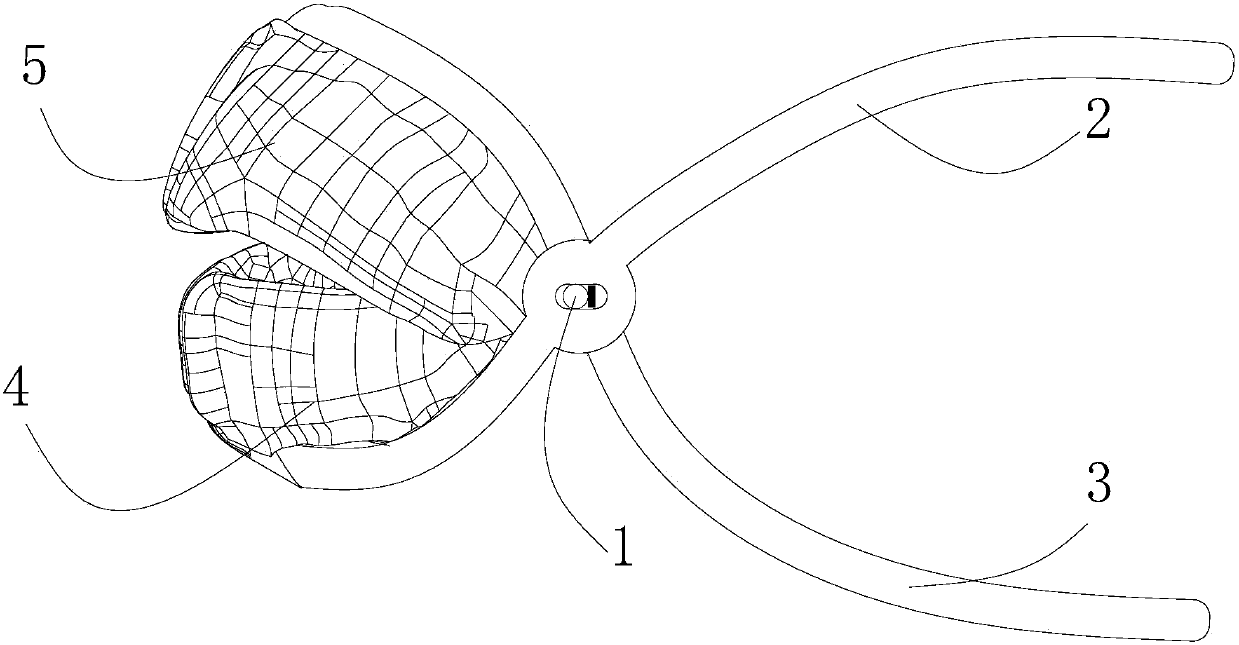
[0030] This embodiment relates to a kind of rescue pliers, such as figure 1 As shown, it includes an upper tong handle 2 and a lower tong handle 3 that are pivotally connected together via a rotating shaft 1, and the upper tong handle 2 and the lower tong handle 3 are respectively formed on the same side of the upper tong handle 2 and the lower tong handle 3 The upper tooth body 4 and the lower tooth body 5 that can be engaged with each other by rotation.

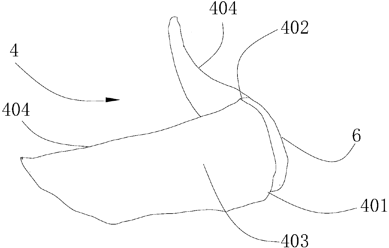
[0031] Such as figure 2 As shown, in this embodiment, the upper tooth body 4 has an upper connecting end 401, and an upper tooth tip 402 is formed on the upper tooth body 4. The upper tooth tip 402 is arranged relative to the upper...


PUM


Abstract

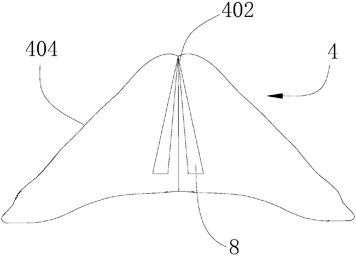
The invention provides forcible entry pliers.The forcible entry pliers comprise an upper plier handle and a lower plier handle which are connected together in a pivot mode through a rotation shaft, the same side of the upper plier handle and the same side of the lower plier handle are provided with an upper tooth body and a lower tooth body respectively, the upper tooth body and the lower tooth body can be meshed with each other due to rotation of the upper plier handle and the lower plier handle and are each provided with a tooth tip, and cutting edges formed by the tooth tips and the upper tooth body and the lower tooth body are in an S shape in the length direction of the cutting edges.According to the forcible entry pliers, when the upper tooth body and the lower tooth body are meshed with each other, stress concentration is formed at the contact positions of an object to be forcibly entered and the upper tooth tip and the lower tooth tip, when the stress strength exceeds the ultimate strength of the object to be forcibly entered, the object to be forcibly entered is firstly broken to form a forcible entry breach, therefore, the cutting difficulty is lowered, and the good forcible entry effect is achieved; meanwhile, the contact area of the cutting edges and the object is increased in the limited geometric space through the S-shaped cutting edges, the load borne by the cutting edges is decreased, and the damage probability of the cutting edges is decreased.

Description

technical field [0001] The invention relates to the technical field of cutting, in particular to a rescue pliers. Background technique [0002] At present, the fire-fighting special hydraulic rescue pliers have good rescue and cutting ability, but the structure is complex and the overall weight of the pliers is large, and it is inconvenient for a single person to operate, which is not conducive to popularization and is expensive. And the hydraulic rescue pliers in the prior art are generally straight-line shearing blades, the structure of the above-mentioned rescue pliers is relatively simple, and there are the following disadvantages in use: (1) a larger force must be applied when in use It is relatively laborious to form a cut-off; (2) the cutting edge is easy to passivate after a period of use, which further increases the difficulty of demolition. Contents of the invention [0003] In view of this, the present invention aims to provide a rescue pliers to improve the re...

Claims


Application Information

Patent Timeline
Patent Type & Authority Patents(China)
IPC IPC(8): B23D29/02B23D35/00
CPCB23D29/02B23D35/001
Inventor 张诗贺
Owner 张诗贺
Learn More