Clamping device for bar grabbing

A technology of clamping device and bar material, which is applied in the direction of workpiece clamping device, positioning device, clamping, etc., can solve the problems of high economic cost, potential safety hazard, waste of energy, etc., to improve operation safety, save economic cost, The effect of increasing friction

Active Publication Date: 2016-07-13
江苏怿盟智能科技有限公司
View PDF6 Cites 2 Cited by
  • Summary
  • Abstract
  • Description
  • Claims
  • Application Information

AI Technical Summary

Problems solved by technology

[0002] The existing clamping device for grabbing bar material, especially the double-claw clamping device usually requires multiple driving sources, sensors and relatively complicated control circuits, which not only wastes energy, but also easily damages the electrical components after working for a long time , also brings some security risks
Most of the existing clamping devices for grabbing bars satisfy the planar motion, but it is easy to cause the bar to drop and shift during the three-dimensional rotary motion
In order to overcome these problems, it is often necessary to put forward higher design requirements and pay higher economic costs for the mechanism, which is the deficiency of the existing technology

Method used


Image

  • Clamping device for bar grabbing
  • Clamping device for bar grabbing
  • Clamping device for bar grabbing

Examples


Embodiment

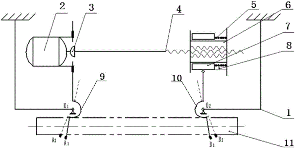
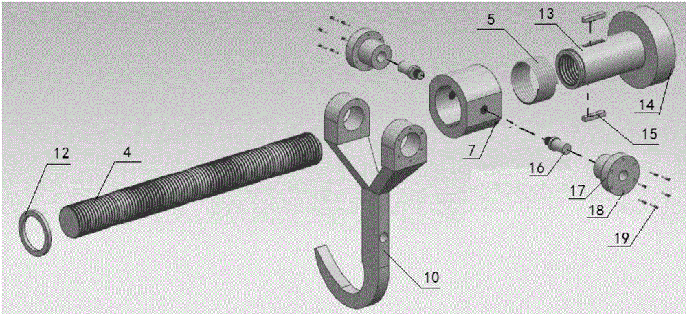
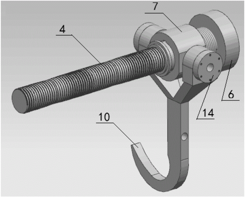
[0018] Example: Such as figure 1 As shown, the present invention discloses a clamping device for grabbing bars, including a frame 1, a driving motor 2, a linkage device, a first claw 9 and a second claw 10, and the driving motor 2 and the linkage device are fixed on the on the above-mentioned frame 1, and the transmission is realized through the screw rod 4; the linkage device includes the swing guide sleeve 7 and the anti-rotation / slip nut 6, the anti-rotation / slip nut 6 includes a threaded mating end 13 and a nut 14, and the anti-rotation A pair of keys 15 are provided on the outer wall of the threaded mating end 13 of the sliding nut 6, and a through groove is provided at the corresponding position on the inner wall of the swing guide sleeve 7, and the swing guide sleeve 7 is sleeved on the anti-rotation / slip joint through the key connection. On the threaded mating end of the nut 6, this structure can realize the relative sliding between the anti-rotation / slip nut 6 and t...


PUM


Abstract

The invention discloses a clamping device for bar grabbing.The clamping device comprises a machine frame, a driving device, a linkage device, a first claw and a second claw, wherein the driving device and the linkage device are fixed to the machine frame, the first claw is connected with the driving device, the second claw is connected with the linkage device, and the driving device is connected with the linkage device through a lead screw.The clamping device is simple in structure and high in stability, bar grabbing and clamping with two claws can be achieved through one power source only, economic cost is reduced, and operation of the clamping device during three-dimensional rotation is achieved; by arranging a damping layer at the position, in contact with a bar, of each claw, friction force between the claws and the bar is improved, shaking off of the bar during grabbing and movement is prevented, and operation safety is improved.

Description

technical field [0001] The invention belongs to the technical field of mechanical equipment and relates to a clamping device, in particular to a clamping device for grabbing bars. Background technique [0002] The existing clamping device for grabbing bar material, especially the double-claw clamping device usually requires multiple driving sources, sensors and relatively complicated control circuits, which not only wastes energy, but also easily damages the electrical components after working for a long time , also brings certain security risks. Most of the existing clamping devices for grabbing bars satisfy the planar motion, but it is easy for the bars to drop and shift during the three-dimensional rotary motion. In order to overcome these problems, it is often necessary to put forward higher design requirements and pay higher economic costs for the mechanism, which is the deficiency of the prior art. Contents of the invention [0003] Purpose of the invention: The pu...

Claims


Application Information

Patent Timeline
Patent Type & Authority Applications(China)
IPC IPC(8): B25B11/00B23Q3/00
CPCB23Q3/00B25B11/00
Inventor 康杰刘远伟朱双艳
Owner 江苏怿盟智能科技有限公司
Why Eureka
Try Eureka