

Robot
A technology of robots and dual steering gears, applied in manipulators, motor vehicles, building structures, etc., can solve the problems of high risk factor, difficult construction, high labor cost, etc., achieve good shock absorption performance, safe and reliable design, and promotion value high effect
- Summary
- Abstract
- Description
- Claims
- Application Information
AI Technical Summary
Problems solved by technology
Method used
Image

Examples
Embodiment 1
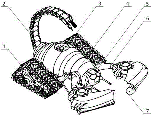
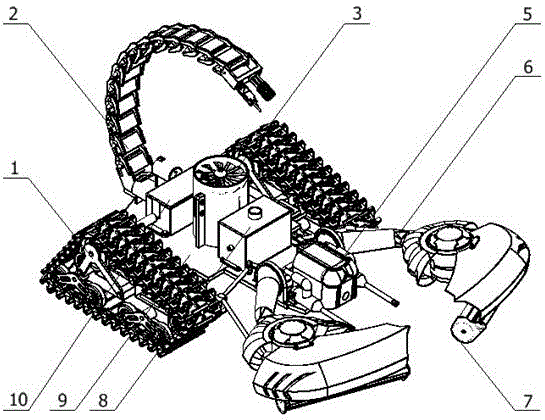
[0049] Embodiment 1: as Figure 1-14 As shown, a robot includes a secondary shock-absorbing triangular crawler 1, a duct adsorption device 3, a casing 4, a head spraying device 5, a double steering gear mechanical arm 6, a coating device 7, a charging box 8, and a bottom plate 9 , dual-motor differential device 10;
[0050] The head spraying device 5 is installed on the front end of the base plate 9, the left and right double steering gear mechanical arms 6 are respectively installed on both sides of the front end of the base plate 9 and a coating device 7 is installed on the double steering gear mechanical arms 6, and the charging box 8 is installed on the base plate 9 neck, the duct adsorption device 3 is installed on the middle part of the base plate 9 through bolt connection, the dual-motor differential device 10 is installed on the abdomen of the base plate 9 through bolt connection, and the secondary shock-absorbing triangular track 1 is installed on the dual-motor diffe...
Embodiment 2
[0064] Embodiment 2: as Figure 1-14 As shown, a robot includes a secondary shock-absorbing triangular crawler 1, a duct adsorption device 3, a casing 4, a head spraying device 5, a double steering gear mechanical arm 6, a coating device 7, a charging box 8, and a bottom plate 9 , dual-motor differential device 10;
[0065] The head spraying device 5 is installed on the front end of the base plate 9, the left and right double steering gear mechanical arms 6 are respectively installed on both sides of the front end of the base plate 9 and a coating device 7 is installed on the double steering gear mechanical arms 6, and the charging box 8 is installed on the base plate 9 neck, the duct adsorption device 3 is installed on the middle part of the base plate 9 through bolt connection, the dual-motor differential device 10 is installed on the abdomen of the base plate 9 through bolt connection, and the secondary shock-absorbing triangular track 1 is installed on the dual-motor diffe...
Embodiment 3
[0071] Embodiment 3: as Figure 1-14 As shown, a robot includes a secondary shock-absorbing triangular crawler 1, a duct adsorption device 3, a casing 4, a head spraying device 5, a double steering gear mechanical arm 6, a coating device 7, a charging box 8, and a bottom plate 9 , dual-motor differential device 10;
[0072] The head spraying device 5 is installed on the front end of the base plate 9, the left and right double steering gear mechanical arms 6 are respectively installed on both sides of the front end of the base plate 9 and a coating device 7 is installed on the double steering gear mechanical arms 6, and the charging box 8 is installed on the base plate 9 neck, the duct adsorption device 3 is installed on the middle part of the base plate 9 through bolt connection, the dual-motor differential device 10 is installed on the abdomen of the base plate 9 through bolt connection, and the secondary shock-absorbing triangular track 1 is installed on the dual-motor diffe...
PUM
 Abstract
Description
Claims
Application Information