Ambient light resisting circuit and method

A technology of ambient light and light-emitting circuits, which is applied in the direction of measuring devices, instruments, special recording/indicating devices, etc., can solve the problems of reducing effective signal components, misidentifying effective signals, and system errors, etc. Effect

Active Publication Date: 2016-07-13
CHENGDU VCARE QINYUAN HEALTH TECH
View PDF5 Cites 0 Cited by
  • Summary
  • Abstract
  • Description
  • Claims
  • Application Information

AI Technical Summary

Problems solved by technology

[0002] In traditional circuits, when the light-emitting tube is not turned on, due to the influence of ambient light, etc., the receiving tube will also generate photocurrent, which will be sampled and identified by the system after conversion, thereby significantly reducing the effective signal component and seriously affecting the system signal-to-noise ratio; even The influence of ambient light is not enough to completely submerge the effective signal. When the ambient light changes periodically, the photocurrent generated by the ambient light on the receiving tube also changes periodically, which is easily misidentified as an effective signal by the system, further deteriorating the signal-to-noise Ratio, it may even make the system recognize the periodic change of ambient light as a valid signal, and recognize the signal generated by the light-emitting tube as noise, resulting in serious system errors

Method used


Image

  • Ambient light resisting circuit and method
  • Ambient light resisting circuit and method
  • Ambient light resisting circuit and method

Examples


Embodiment Construction

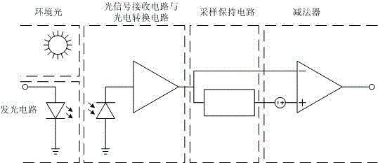
[0020] Describe technical scheme of the present invention in further detail below in conjunction with accompanying drawing: as figure 1 Shown, a kind of ambient light resistance circuit, it comprises light-emitting circuit, optical signal receiving circuit, photoelectric conversion circuit, sample hold circuit and subtractor; The input end of described light-emitting circuit accepts external input signal, and light-emitting circuit receives light signal The first optical signal sent by the circuit, the optical signal receiving circuit receives the first optical signal from the light emitting circuit and the second optical signal from the external ambient light, the output end of the optical signal receiving circuit is connected with the photoelectric conversion circuit, and the photoelectric conversion The first output terminal of the circuit is connected with the inverting input terminal of the subtractor, the second output terminal of the photoelectric conversion circuit is c...


PUM


Abstract

The invention discloses an ambient light resisting circuit and method, and the circuit comprises a light-emitting circuit, an optical signal receiving circuit, a photovoltaic conversion circuit, a sampling holding circuit, and a subtracter. The input end of the light-emitting circuit receives an external input signal, and the light-emitting circuit transmits a first optical signal to the optical signal receiving circuit. The optical signal receiving circuit receives the first optical signal from the light-emitting circuit, and a second optical signal from the external ambient light. The output end of the optical signal receiving circuit is connected with the photovoltaic conversion circuit. The output end of the photovoltaic conversion circuit is connected with an inverted phase input end of the subtracter, and the second output end of the photovoltaic conversion circuit is connected with the sampling holding circuit. The output end of the sampling holding circuit is connected with the in-phase input end of the subtracter. The output end of the subtracter outputs a result. The circuit achieves the inhibition of ambient light, effectively enlarges the application range, and improves the capability of resisting environment interferences.

Description

technical field [0001] The invention relates to an ambient light resistance circuit and a method thereof. Background technique [0002] In the traditional circuit, when the light-emitting tube is not turned on, due to the influence of ambient light, etc., the receiving tube will also generate photocurrent, which will be sampled and identified by the system after conversion, thereby significantly reducing the effective signal component and seriously affecting the system signal-to-noise ratio; even The influence of ambient light is not enough to completely submerge the effective signal. When the ambient light changes periodically, the photocurrent generated by the ambient light on the receiving tube also shows periodic changes. It is easy to be misidentified as an effective signal by the system, further deteriorating the signal-to-noise The ratio may even cause the system to recognize the periodic change of ambient light as a valid signal, and recognize the signal generated by...

Claims


Application Information

Patent Timeline
Patent Type & Authority Applications(China)
IPC IPC(8): G01D3/032
CPCG01D3/032
Inventor 崔予红
Owner CHENGDU VCARE QINYUAN HEALTH TECH
Why Eureka
Try Eureka