Textile dirt pressing device

A dirty and hollow technology, applied in the direction of presses, manufacturing tools, etc., can solve difficult problems

Inactive Publication Date: 2018-12-18
王秀丽
View PDF7 Cites 0 Cited by
  • Summary
  • Abstract
  • Description
  • Claims
  • Application Information

AI Technical Summary

Problems solved by technology

[0002] The textile printing and dyeing industry is a major player in the discharge of industrial sewage. The sewage mainly contains dirt, grease, salt on textile fibers, and various sizing materials, dyes, surfactants, additives, acids and bases added during processing. Textile sewage treatment is to discharge the textile sewage directly into the sedimentation tank for treatment, because the sewage contains large cloth scraps, cloth strips and other debris, and the fished out debris will store a large amount of sewage, which is extremely difficult to treat together

Method used


Image

  • Textile dirt pressing device
  • Textile dirt pressing device
  • Textile dirt pressing device

Examples


specific Embodiment approach

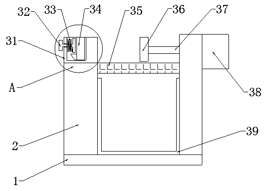
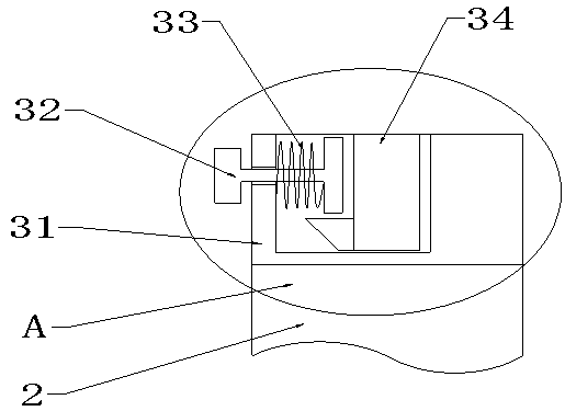
[0021] Specific implementation method: when using, the user should first fix the inserting plate 34 into the concave groove plate 31, the user first holds the inserting plate 34 and moves it downward, and the downward movement of the inserting plate 34 drives the triangular block to move downward. When the triangular block moves down to the upper side of the pull rod 32, continue to move the insert plate 34 downward, the triangular block produces a leftward force on the pull rod 32, and the pull rod 32 moves to the left under the leftward force, and the pull rod 32 moves to the left Cause the spring 33 to compress and generate elastic force. When the triangular block moves down to the lower side of the pull rod 32, the pull rod 32 moves to the right under the force of the spring 33. When the pull rod 32 moves right to its right end surface and the left end surface of the insert plate 34 When in close contact, the pull rod 32 stops moving, thereby realizing the function of fixin...


PUM


Abstract

The invention provides a textile dirt pressing device. The textile dirt pressing device comprises a base, a hollow box, concave groove plates, pull rods, springs, an insertion plate, a filter screen,a push plate, a push rod and an electric cylinder; the hollow box is fixed at the upper end of the base; the filter screen is arranged in the hollow box; the push plate is mounted on the upper side ofthe filter screen; the push rod is fixed at the middle part of the right end surface of the push plate; the push rod penetrates through the right end surface of the hollow box; the electric cylinderis fixed on the right end surface of the hollow box; the concave groove plates are welded at the left parts of the front and back end surfaces in the hollow box; the front and back ends of the insertion plate are mounted in the concave groove plates; the concave groove plates are arranged on the left side of the push plate; the pull rods are arranged on the left side of the insertion plate; and the springs sleeve the outer sides of the pull rods. Through the design, the textile dirt pressing device achieves the function of pressing textile dirt; and the textile dirt pressing device is convenient to use and operate, achieves the textile dirt pressing function, and is high in reliability.

Description

technical field [0001] The invention is a textile dirt suppressing device, which belongs to the field of textile machinery and equipment. Background technique [0002] The textile printing and dyeing industry is a major player in the discharge of industrial sewage. The sewage mainly contains dirt, grease, salt on textile fibers, and various sizing materials, dyes, surfactants, auxiliaries, acids and bases added during processing. Textile sewage treatment is to discharge textile sewage directly into the sedimentation tank for treatment, because the sewage contains large cloth scraps, cloth strips and other debris, and the fished out debris will store a large amount of sewage, which is extremely difficult to treat together. Contents of the invention [0003] Aiming at the deficiencies in the prior art, the object of the present invention is to provide a textile dirt suppression device to solve the problems raised in the above-mentioned background technology. The invention is...

Claims


Application Information

Patent Timeline
Patent Type & Authority Applications(China)
IPC IPC(8): B30B9/06B30B15/00
CPCB30B9/06B30B15/00B30B15/0082
Inventor 王秀丽
Owner 王秀丽
Why Eureka
Try Eureka