
Electronic screen assembling equipment for electronic product

A technology for electronic products and assembly equipment, applied in metal processing equipment, devices for coating liquid on surfaces, metal processing, etc., can solve the problems of high assembly cost, low assembly efficiency, etc., to improve assembly efficiency, enhance functionality and The effect of practicality

Inactive Publication Date: 2021-08-13
HUANGSHAN UNIV
View PDF0 Cites 0 Cited by
  • Summary
  • Abstract
  • Description
  • Claims
  • Application Information

AI Technical Summary

Problems solved by technology

Because the early products are mainly based on electronic tubes, they are called electronic products, and many electronic products need to be installed with electronic screens as the main body of display and operation, adding vitality to electronic products, improving the functionality of electronic products, and can also be used as the main body of display. , showing the performance and working status of electronic products at all times, and electronic screens are mostly installed on the corresponding motherboards to connect with electronic products. During the installation process of electronic screens and motherboards, screws are also needed for fastening installation. The safety of the use of the electronic screen will also be equipped with a corresponding protective cover, and then the electronic screen will be installed in the corresponding position in the electronic product. However, in the assembly of the existing electronic screen, due to the need to grasp the electronic screen, screws and protective cover and other components are mostly assembled manually to facilitate loading, which leads to lower actual assembly efficiency and higher assembly costs

Method used


Image

  • Electronic screen assembling equipment for electronic product
  • Electronic screen assembling equipment for electronic product
  • Electronic screen assembling equipment for electronic product

Examples


Embodiment Construction

[0036] In order to enable those skilled in the art to better understand the technical solutions of the present invention, the present invention will be further described in detail below in conjunction with the accompanying drawings.

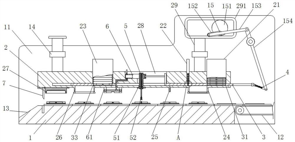
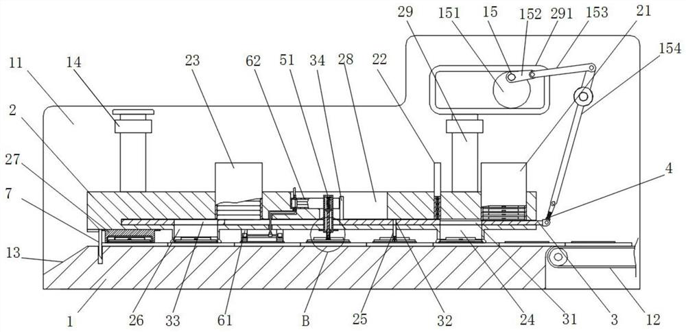
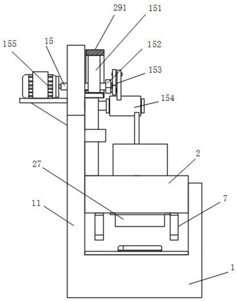
[0037] The present invention provides such as Figure 1-7 The electronic screen assembly equipment for electronic products shown includes a conveying platform 1, a side vertical plate 11 is fixedly connected to the outside of the top of the conveying platform 1, and a lifting processing seat 2 is slidably installed inside the side vertical plate 11. The top of one end of the side vertical plate 11 is rotatably equipped with a drive shaft 15, and the outside of the side vertical plate 11 is fixedly equipped with a drive motor 155, which is connected to the drive shaft 15 in transmission, and the top of the lifting processing seat 2 A guide plate 29 is fixedly connected, and a movable frame 291 is fixedly installed on the top of the guide plate 29,...


PUM


Abstract

The invention discloses electronic screen assembling equipment for an electronic product, and relates to the technical field of electronic product production. The electronic screen assembling equipment comprises a conveying table, wherein a side vertical plate is fixedly connected to the outer side of the top of the conveying table, a lifting machining seat is slidably mounted in the side vertical plate, and a driving shaft is rotatably mounted at the top of one end of the side vertical plate; and a driving motor is fixedly installed outside the side vertical plate and is in transmission connection with the driving shaft, and a guide plate is fixedly connected to the top of the lifting machining seat. Through cooperation of an eccentric rotating wheel and a movable frame and linkage of a rocker, a pull rod and a swing rod, lifting control over the lifting machining base and left-right movement control over a transverse moving plate are achieved; and through left-right movement of a screen replacement groove, a screw replacement hole and a protective cover replacement groove, the automatic assembling and feeding function is completed, so that the assembling efficiency of the electronic screen is improved, and the functionality and practicability of equipment use are enhanced.

Description

technical field [0001] The invention relates to the technical field of electronic product production, in particular to electronic screen assembly equipment for electronic products. Background technique [0002] Electronic products are related products based on electric energy, mainly including: watches, smart phones, telephones, televisions, video disc players (VCD, SVCD, DVD), video recorders, camcorders, radios, tape recorders, combination speakers, CD players (CD), computers, game consoles, mobile communication products, etc. Because the early products are mainly based on electronic tubes, they are called electronic products, and many electronic products need to be installed with electronic screens as the main body of display and operation, adding vitality to electronic products, improving the functionality of electronic products, and can also be used as the main body of display. , to display the performance and working status of electronic products at all times, and ele...

Claims


Application Information

Patent Timeline
IPC IPC(8): B23P19/00B23P19/06B05C1/02B05C11/10
CPCB05C1/027B05C11/10B23P19/001B23P19/06
Inventor 张晓利
Owner HUANGSHAN UNIV
Learn More