Corrosion rate measuring device and measuring method

A corrosion rate and measuring device technology, applied in measuring devices, weather resistance/light resistance/corrosion resistance, instruments, etc., can solve the problem of inability to maintain or replace metal components, inability to know the corrosion degree of metal components in time, and inability to measure metal component corrosion in real time Speed ​​and other issues

Inactive Publication Date: 2016-07-13
ELECTRIC POWER RESEARCH INSTITUTE, CHINA SOUTHERN POWER GRID CO LTD +1
View PDF6 Cites 7 Cited by
  • Summary
  • Abstract
  • Description
  • Claims
  • Application Information

AI Technical Summary

Problems solved by technology

Although the corrosion rate of metal components can be measured by the above method, it takes 1 to 2 years to measure the corrosion rate of metal components through the metal coupon exposure test, so it is impossible to measure the corrosion rate of metal components in real time, and it is impossible to know the corrosion rate of metal components in time. Corrosion level, unable to maintain or replace corroded metal components in time

Method used


Image

  • Corrosion rate measuring device and measuring method
  • Corrosion rate measuring device and measuring method
  • Corrosion rate measuring device and measuring method

Examples


Embodiment 1

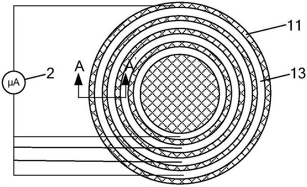
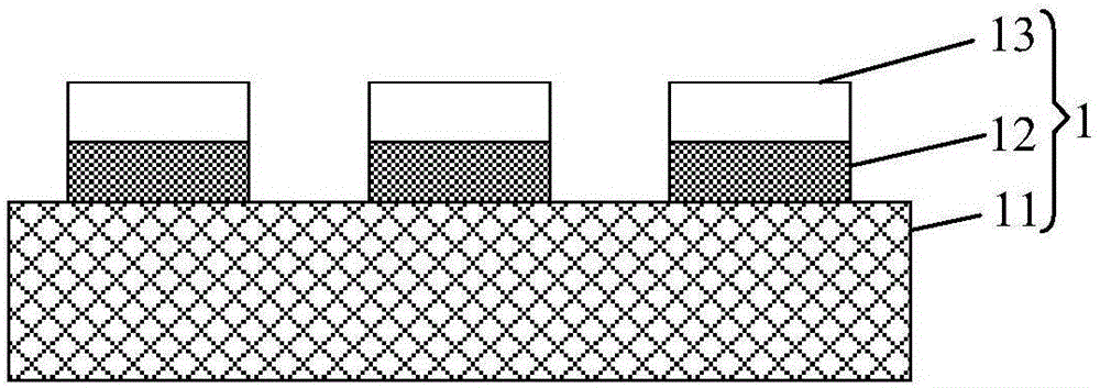
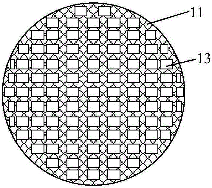
[0025] Embodiments of the present invention provide a corrosion rate measuring device, such as figure 1 As shown, the corrosion rate measuring device includes at least one measuring probe 1 and at least one ammeter 2, specifically, as figure 2 As shown, the measuring probe 1 includes a substrate 11, an insulating layer 12 and a metal layer 13; wherein, the insulating layer 12 is located on the substrate 11, the metal layer 13 is located on the insulating layer 12, and the projection of the insulating layer 12 and the metal layer 13 on the substrate 11 All fall in the substrate 11, the negative terminal of the ammeter 2 is connected to the substrate 11, and the positive terminal of the ammeter 2 is connected to the metal layer 13; the substrate 11 is an active metal or an active metal alloy; the metal layer 13 is an inert metal layer.

[0026] The process of using the above corrosion rate measuring device to measure the corrosion rate of metal components is as follows:

[002...

Embodiment 2

[0044] An embodiment of the present invention provides a corrosion rate measurement method, using the corrosion rate measurement device in Embodiment 1 of the present invention for corrosion rate measurement, the corrosion rate measurement method includes:

[0045] Step S1, measure the magnitude of all the currents generated between the substrate and the metal layer with an ammeter.

[0046] Step S2. According to the current data and the material of the substrate, the corrosion rate of the substrate during the test period is obtained. The current data includes the magnitude of all currents and the duration of each current measured by the ammeter.

[0047] Exemplarily, according to the current data and the material of the substrate, the specific steps of obtaining the corrosion rate of the substrate during the test cycle include:

[0048] According to the magnitude of all currents and the duration of each current, the number Q of electrons transferred between the substrate and ...


PUM


Abstract

The invention discloses a corrosion rate measuring device and measuring method, and relates to the technical field of electrical equipment corrosion, and the technical problem that in the prior art, the corrosion rate of a metal component cannot be measured in real time is solved.The corrosion rate measuring device comprises at least one measuring probe and at least one ampere meter, and each measuring probe comprises a base body, an insulating layer and a metal layer, wherein the insulating layer is located on the base body, the metal layer is located on the insulating layer, the area of the insulating layer and the area of the metal layer are both smaller than that of the base body, a negative terminal of each ampere meter is connected with the corresponding base body, and a positive terminal of each ampere meter is connected with the corresponding metal layer; each base body is made of active metal or active metal alloy, and the metal layers are inert metal layers.The corrosion rate measuring device and measuring method are used for measuring the corrosion rate of the metal component in real time.

Description

technical field [0001] The invention relates to the technical field of electric equipment corrosion, in particular to a corrosion rate measuring device and a measuring method. Background technique [0002] With the rapid development of society, people's demand for electricity is increasing, and it is becoming more and more important to ensure the timeliness and safety of power transmission. However, for areas with a humid climate, power equipment such as substations is in a humid environment for a long time, which will cause the metal components in the power equipment to be corroded by water vapor in the humid environment, resulting in a significant decline in the performance of the power equipment and seriously affecting The timeliness and safety of power transmission. Therefore, it is necessary to monitor the corrosion rate of the metal components in time, and to know the corrosion degree of the metal components according to the corrosion rate of the metal components, so ...

Claims


Application Information

Patent Timeline
Patent Type & Authority Applications(China)
IPC IPC(8): G01N17/02G01N17/04
CPCG01N17/02G01N17/04
Inventor 孟晓波廖永力邹林李锐海陈晓张巍吴新桥张贵峰龚博张曦朱烨
Owner ELECTRIC POWER RESEARCH INSTITUTE, CHINA SOUTHERN POWER GRID CO LTD
Why Eureka
Try Eureka