
Novel high-precision MEMS accelerometer

An accelerometer and acceleration technology, applied in speed/acceleration/shock measurement, acceleration measurement, instruments, etc., can solve problems such as loop filter mismatch, large dispersion, and difficult to control accurately, and achieve the goal of reducing the number of ADC digits Requirements, suppression of noise interference, optimal parameters

Active Publication Date: 2016-07-13
INST OF GEOLOGY & GEOPHYSICS CHINESE ACAD OF SCI
View PDF2 Cites 6 Cited by
  • Summary
  • Abstract
  • Description
  • Claims
  • Application Information

AI Technical Summary

Benefits of technology

This technology improves on existing sensors with improved performance compared to current methods such as linear or rotational acceleration measurement systems. It achieves this by implementing an electronic device called a ring oscillator (RON), instead of just one component like other components. By controlling these factors based on input signals from external sources, better matching between detected values can be achieved without compromising precision. Additionally, the use of advanced techniques allows for precise parameter tunings within the feedback path of the controlled process. Overall, this innovation enhances the overall functionality and reliability of the detective devices while reducing their cost.

Problems solved by technology

This patented describes a problem that arises when implementing conventional electrostatic inertia sensory systems (ESIAS). Specifically, these devices require precise measurements over long periods of operation without losing data or causing instabilities during use. Current solutions involve expensive components like inductive pressure transducers, but they lack flexibility and adaptable features. Therefore there needs improvement techniques to address issues related to current ESI AS technologies including reduced cost, increased functionality, improved efficiency, better linear response, higher resolution capabilities, etc., while also improving overall performance.

Method used


Image

  • Novel high-precision MEMS accelerometer
  • Novel high-precision MEMS accelerometer
  • Novel high-precision MEMS accelerometer

Examples


Embodiment Construction

[0058] In order to make the object, technical solution and advantages of the present invention clearer, the present invention will be further described in detail below in conjunction with the accompanying drawings and embodiments. It should be understood that the specific embodiments described here are only used to explain the present invention, not to limit the present invention.

[0059] On the contrary, the invention covers any alternatives, modifications, equivalent methods and schemes within the spirit and scope of the invention as defined by the claims. Further, in order to make the public have a better understanding of the present invention, some specific details are described in detail in the detailed description of the present invention below. The present invention can be fully understood by those skilled in the art without the description of these detailed parts.

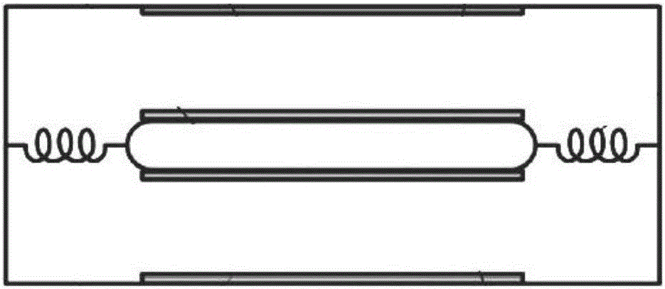
[0060] Reference attached image 3 , with MEMS accelerometer especially "sandwich" type (attached f...


PUM


Abstract

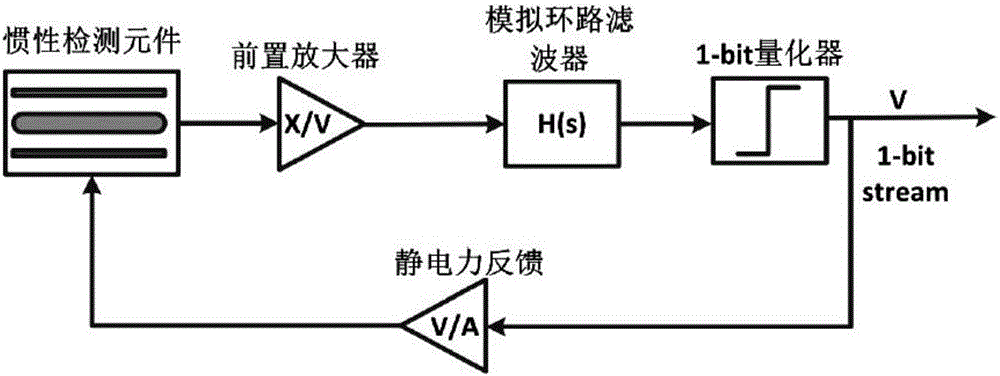
The invention relates to an accelerometer, in particular to an MEMS accelerometer. Specifically, a high speed digital quantization unit is embedded in a sigma-delta full closed-loop circuit of the MEMS accelerometer, and through signal estimation and processing, an MEMS full closed-loop sigma-delta system consisting of a low bit quantizer can achieve full digital closed-loop and high bit digital quantization output. Through a signal processing algorithm and the system stability design, the invention achieves digital feedback while achieving feedback electrostatic force quantization. Meanwhile, a loop filter is realized in a digital manner, an integral windup phenomenon generated by an analog loop filter can be avoided, the layout design difficulty and the influence of noises force the analog loop filter on the system are also reduced, and Tehran performance of the MEMS accelerometer is effectively improved.

Description


Claims


Application Information

Patent Timeline
Owner INST OF GEOLOGY & GEOPHYSICS CHINESE ACAD OF SCI
Learn More