Large view field push-broom constant ground element remote sensing camera system

A remote sensing camera, push-broom technology, used in parts, TVs, electrical components, etc. of TV systems

Inactive Publication Date: 2016-07-13
SHANGHAI INST OF TECHNICAL PHYSICS - CHINESE ACAD OF SCI
View PDF5 Cites 8 Cited by
  • Summary
  • Abstract
  • Description
  • Claims
  • Application Information

AI Technical Summary

Problems solved by technology

[0003] The main purpose of this system is to solve the problem that the ground resolution of the edge field of view of the lar

Method used


Image

  • Large view field push-broom constant ground element remote sensing camera system
  • Large view field push-broom constant ground element remote sensing camera system
  • Large view field push-broom constant ground element remote sensing camera system

Examples


Embodiment Construction

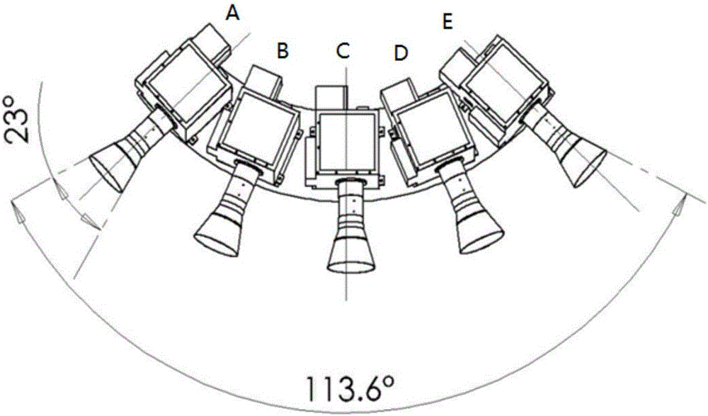
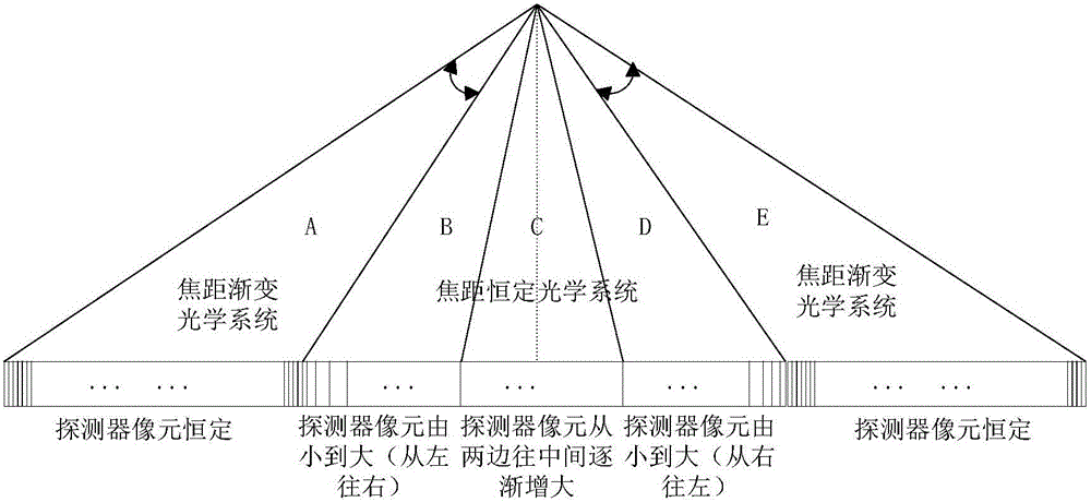
[0020] According to the large field of view push-broom Henderson remote sensing camera system described in the summary of the invention, the whole system is composed of five sub-cameras, wherein sub-cameras A and E are composed of a zoom optical system and a CCD detector with a constant pixel size, and sub-camera B , C, and D are composed of a fixed-focus optical system and a CCD detector with a gradual change in pixel size:

[0021] The zoom optical system of the sub-cameras A and E has a concentric primary mirror with a diameter of 100mm. There are 8 micro-cameras spliced ​​at the rear to form a 23° field of view. The field of view of each micro-camera is 3.5°. The focal lengths of the 8 micro-camera arrays are respectively 256mm, 185mm, 144mm, 118mm, 99.5mm, 86.2mm, 76mm and 68.5mm, CCD detector pixel size is 20um, line size is 2351×1;

[0022] The aperture of the fixed-focus optical system of sub-cameras B and D is 25mm, the focal length is 62.5mm, the pixel size of the CC...


PUM


Abstract

The invention discloses a large view field push-broom constant ground element remote sensing camera system. The system comprises the following parts: a large view field camera is formed by splicing five sub-cameras, each sub-camera has the same view field and different instantaneous view field, and the instantaneous view field of each sub-camera changes with the field angle, wherein the sub-camera C images a sub-satellite point, the sub-camera A and E, B and D are respectively symmetrically arranged on two sides of the sub-camera C, the sub-camera A and E are formed by a zoom optical system and a CCD detector with a constant pixel size, and the sub-camera B, C and D are formed by a fixed focus optical system and a CCD detector with pixel in gradually varied size. The advantages of the camera system comprises: the camera has large view field, the ground coverage area is wide, and the ground resolution is constant and consistent in whole view field range.

Description

Technical field: [0001] The invention relates to field of view splicing technology, detector design technology, optical design technology, etc., and specifically refers to a large field of view push-broom constant earth element remote sensing camera system, which can be widely used in space remote sensing instruments. Background technique: [0002] Achieving a large field of view and ultra-wide ground coverage is of great practical significance for aerospace remote sensing satellites. However, due to the influence of the curvature of the earth, the ground resolution of sub-satellite points and edge field of view in the direction of orbit often deviates greatly, and the field of view The larger the deviation, the greater the deviation will be. For example, when the ground resolution of the sub-satellite point is 400m, the ground resolution for the 56.8° edge field of view reaches 2987m. If an unexpected event happens near the edge field of view, due to the ground resolution I...

Claims


Application Information

Patent Timeline
IPC IPC(8): G03B37/04H04N5/247
CPCG03B37/04H04N23/90
Inventor 谭婵刘云猛裴浩东丁雷
Owner SHANGHAI INST OF TECHNICAL PHYSICS - CHINESE ACAD OF SCI
Why Eureka
Try Eureka