Near-to-eye display optical system

A display system and optical system technology, applied in the field of optical engineering, can solve the problems of small exit pupil diameter, small field of view, bulky system, etc., and achieve the effect of simple manufacture, large field of view, and small overall size

Pending Publication Date: 2020-07-10
GUANGGAN SHANGHAI TECH CO LTD
View PDF1 Cites 6 Cited by
  • Summary
  • Abstract
  • Description
  • Claims
  • Application Information

AI Technical Summary

Problems solved by technology

[0005] The present invention provides a near-eye display optical system to solve the problems of the existing AR glasses with small field of view, small exit pupil diameter and bulky system

Method used


Image

  • Near-to-eye display optical system
  • Near-to-eye display optical system
  • Near-to-eye display optical system

Examples


specific Embodiment approach 1

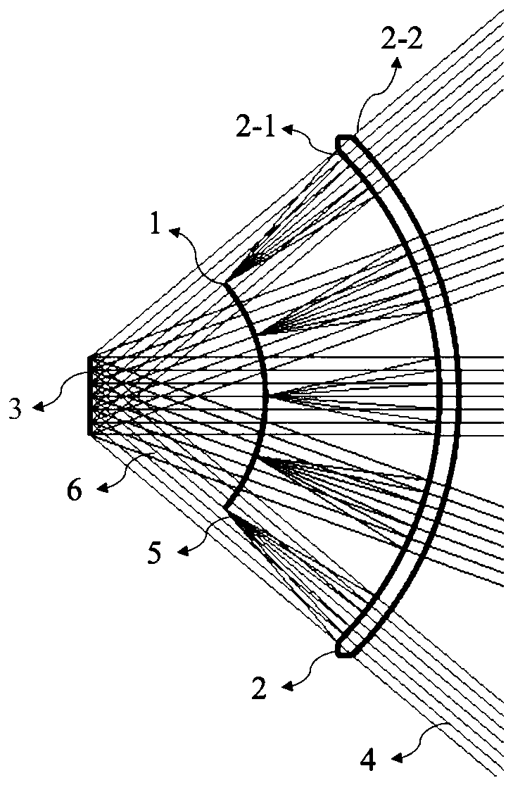
[0035] Specific implementation mode 1. Combination Figure 1 to Figure 10 Describe this embodiment, a near-eye display optical system, including a display system 1 and a spherical reflective lens 2; place the display system 1 in front of the pupil 3 at the reference position, and place the spherical reflective lens 2 in front of the display system 1; in the display system 1 The display pixels are distributed on the convex surface, and the display pixels in the display system 1 emit light to the spherical reflector 2, and the spherical reflector 2 reflects the light to the pupil 3 at the reference position; The image is generated by the middle light, and the image is magnified by the spherical mirror 2 and reflected to the pupil 3 at the reference position. The spherical mirror 2 has two surfaces, the first surface is a partially reflective surface 2-1, which is used to enlarge the image on the display system 1 and place it in the visible range of the human eye, and the reflect...

specific Embodiment approach 2

[0053] Specific embodiment two, combine figure 1 and Figure 11 This embodiment is described. This embodiment is another embodiment of the near-eye display optical system described in the first embodiment: it includes a display system 1 and a spherical mirror 2;

[0054] The spherical mirror 2 has two surfaces, the first surface is a partially reflective surface 2-1, which is used to enlarge the image on the display system 1 and place it in the visible range of the human eye, and the reflectivity can be in the range of 1%-99% %, the second surface is the transmission surface 2-2, which is used to correct the ambient light to suit the degree of the wearer. The position of partly reflective surface and transmissive surface can be interchanged;

[0055] A display system 1 is placed in front of the pupil 3 at the reference position, and a spherical reflector 2 is arranged in front of the display system 1. The display system 1 is located on the focal plane of the spherical reflec...

specific Embodiment approach 3

[0059] Specific embodiment three, combine figure 1 , figure 2 and Figure 12 Describe this embodiment, this embodiment is another embodiment of a near-eye display optical system described in the first embodiment: it includes a display system 1, a spherical mirror 2 and a pupil 3 at a reference position; it adopts a coaxial symmetric form, and the reference The display system 1 is placed in front of the pupil 3, and the spherical reflector 2 is arranged in front of the display system 1. The display system 1 is located on the focal plane of the spherical reflector 2, and the centers of the display system 1 and the spherical reflector 2 are both reference position pupils. 3 near the center, within 1 cm; the spherical mirror 2 has two surfaces, the surface close to the display system is a partial reflection surface 2-1, and its reflectivity can be between 1% and 99%. The surface away from the display system is the transmission surface 2-2, which is used to correct the ambient l...


PUM

PropertyMeasurementUnit
radiusaaaaaaaaaa
reflectanceaaaaaaaaaa

Abstract

The invention provides a near-to-eye display optical system, relates to the field of optical engineering, and solves the problems of small field angle, small exit pupil diameter and cumbersome systemof the existing AR glasses. The near-to-eye display optical system comprises a display system and a spherical reflecting lens. The spherical reflecting lens is provided with two surfaces, the first surface is a partial reflecting surface, and the second surface is a transmission surface; the display system is placed in front of the pupil and located on the focal plane of the spherical reflecting lens, and the sphere centers of the display system and the spherical reflecting lens are both located within the range of 1 cm from the center of the pupil; the display system comprises linear array display pixels pasted on a transparent substrate, a substrate extension part on the outer edge of the transparent substrate, an outer frame, a driving system and an electronic control system. The driving system comprises a driven gear, a driving gear, a rotary bearing and a motor. A large field angle, a large exit pupil diameter and high resolution can be realized, and the glasses are light, easy tomanufacture, low in cost, easy to realize, stable in component fixation and structure and free of stray light interference.

Description

technical field [0001] The invention relates to the field of optical engineering, in particular to a near-eye display optical system. Background technique [0002] The near-eye display system can provide people with virtual images, the most important of which is Augmented Reality (AR for short), which is a new technology that "seamlessly" integrates real world information and virtual world information. Augmented reality glasses are the main implementation of AR. It can provide users with a large picture and 3D effect. It has the potential to replace existing display and computing terminals such as mobile phones, computers and televisions, and has very broad application prospects. [0003] At present, there are a variety of AR technologies, including off-axis catadioptric structures, free-form surface prisms, waveguide glasses, etc., due to the constraints of Lagrangian invariants, it is difficult to solve the problem of large field of view, large exit pupil diameter and vo...

Claims


Application Information

Patent Timeline
Patent Type & Authority Applications(China)
IPC IPC(8): G02B27/01
CPCG02B27/0172G02B2027/0178
Inventor 杨建明
Owner GUANGGAN SHANGHAI TECH CO LTD
Why Eureka
Try Eureka