
Charger and wire coiling structure capable of locking unlocking

An unlocking and self-locking technology, applied in the field of take-up, can solve the problems of affecting the take-up function, the inner core is easy to rotate, etc.

Inactive Publication Date: 2016-07-13
OCEANS KING LIGHTING SCI&TECH CO LTD +3
View PDF6 Cites 10 Cited by
  • Summary
  • Abstract
  • Description
  • Claims
  • Application Information

AI Technical Summary

Problems solved by technology

[0003] However, after the traditional take-up action is completed, the inner core of the take-up device is easy to rotate under the action of external force, so that the collected cable is released again, which affects the take-up function

Method used


Image

  • Charger and wire coiling structure capable of locking unlocking
  • Charger and wire coiling structure capable of locking unlocking
  • Charger and wire coiling structure capable of locking unlocking

Examples


Embodiment Construction

[0033] In order to make the above objects, features and advantages of the present invention more comprehensible, specific implementations of the present invention will be described in detail below in conjunction with the accompanying drawings. In the following description, numerous specific details are set forth in order to provide a thorough understanding of the present invention. However, the present invention can be implemented in many other ways different from those described here, and those skilled in the art can make similar improvements without departing from the connotation of the present invention, so the present invention is not limited by the specific implementations disclosed below.

[0034] It should be noted that when an element is referred to as being “fixed” to another element, it can be directly on the other element or there can also be an intervening element. When an element is referred to as being "connected to" another element, it can be directly connected ...


PUM


Abstract

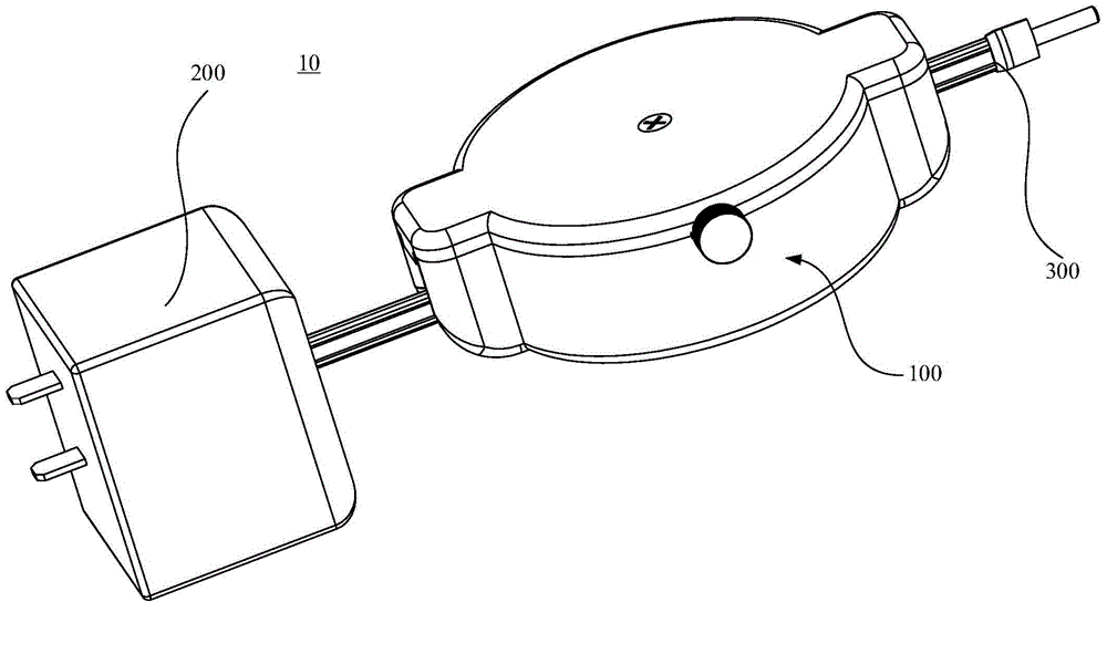
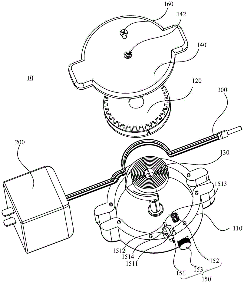
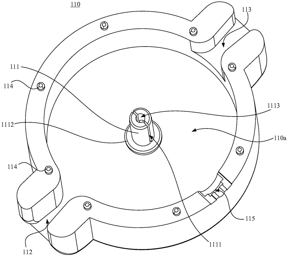
A wire coiling structure capable of locking and unlocking includes a bottom box, an inner core, a volute spring, a cover plate and a pawl assembly. The bottom part of the bottom box protrudes towards the inner side of the box and forms a protruding shaft. A first clamping groove is formed in the protruding shaft in the axial direction. The inner core is provided with a fixed board, a ratchet wheel and a wire arrangement wall body. The ratchet wheel and the wire arrangement wall body are arranged on two faces of the fixed board. A second clamp groove is arranged in the wire arrangement wall body. Two ends of the volute spring are respectively fixed in the first clamping groove and the second clamping groove. The cover board is arranged at the opening end of the bottom box in a covering manner. The pawl assembly includes a pawl, a spring and a knob. The spring sleeves the pawl. The knob is connected with one end of the pawl. The other end of the pawl extends into the bottom box to fit with the pawl. A wire coils the wire arrangement wall body of the inner core and the coiling and uncoiling of the wire are realized by utilizing the elastic potential of the volute spring. The pawl and the ratchet wheel fit with each other so as to realize locking and unlocking. At the same time, the invention also provides a charger employing the coiling structure capable of locking and unlocking.

Description

technical field [0001] The invention relates to the field of wire take-up technology, in particular to a charger and a wire take-up structure capable of self-locking and unlocking. Background technique [0002] Portable lamps need centralized charging management during charging and use. Due to the large number of chargers, it is easy to cause the charging cables to be entangled with each other, which brings inconvenience to centralized charging management. At present, the take-up device is mainly used to solve the problem of intertwining between charging cables. [0003] However, after the traditional wire take-up action is completed, the inner core of the wire take-up device is easy to rotate under the action of an external force, so that the collected cable is released again, which affects the wire take-up function. Contents of the invention [0004] Based on this, it is necessary to address the above problems and provide a self-locking and unlocking charger and a self-...

Claims


Application Information

Patent Timeline
Patent Type & Authority Applications(China)
IPC IPC(8): H01R13/72H02J7/00
Inventor 周明杰庞磊
Owner OCEANS KING LIGHTING SCI&TECH CO LTD
Learn More