
Sampling circuit and sampling method

A sampling circuit and resistance technology, applied in the direction of electrical components, adjusting electrical variables, output power conversion devices, etc., can solve the problems of bandwidth reduction, increasing the capacitive load of the switching booster circuit 100, affecting the stability of the front-stage circuit, etc. Achieve the effect of reducing rotation time, improving sampling accuracy and sampling linearity

Active Publication Date: 2018-10-26
REALTEK SEMICON CORP
View PDF9 Cites 0 Cited by
  • Summary
  • Abstract
  • Description
  • Claims
  • Application Information

AI Technical Summary

Problems solved by technology

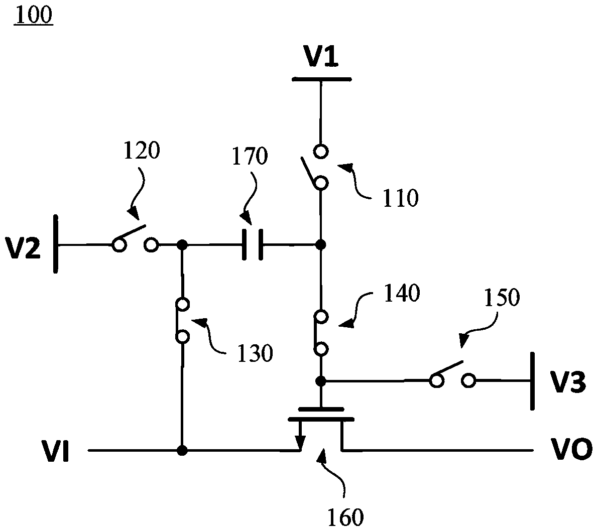
However, this capacitive element 170 also increases the capacitive load of the switching booster circuit 100 at the same time.
More seriously, in a multi-bit application circuit, when a plurality of switch booster circuits 100 are connected in parallel, the front-end circuit will encounter a larger capacitive load, which will affect the output voltage of the front-end circuit (that is, the switch The stability of the input voltage VI) of the booster circuit 100, such as the phase margin (phase margin) becomes worse or the bandwidth drops, thereby affecting the sampling accuracy of the switching booster circuit 100
Furthermore, due to the increase of the capacitive load, the turnaround time required for the sampling signal of the switch booster circuit 100 will also increase, resulting in the deterioration of the sampling linearity of the switch booster circuit 100

Method used


Image

  • Sampling circuit and sampling method
  • Sampling circuit and sampling method
  • Sampling circuit and sampling method

Examples


Embodiment Construction

[0021] The technical terms in the following explanations refer to the customary terms in this technical field. If some terms are explained or defined in this manual, the explanations or definitions of this part of the terms shall prevail.

[0022] The disclosed content of the present invention includes a sampling circuit and a sampling method, which can make the input end of the sampling circuit encounter smaller capacitive loads. On the premise that implementation is possible, those skilled in the art can select equivalent components or steps to implement the present invention according to the disclosure in this specification, that is, the implementation of the present invention is not limited to the following embodiments. Since some elements included in the sampling circuit of the present invention may be known elements individually, the details of the known elements will be omitted in the following description without affecting the full disclosure and implementability of the...


PUM


Abstract

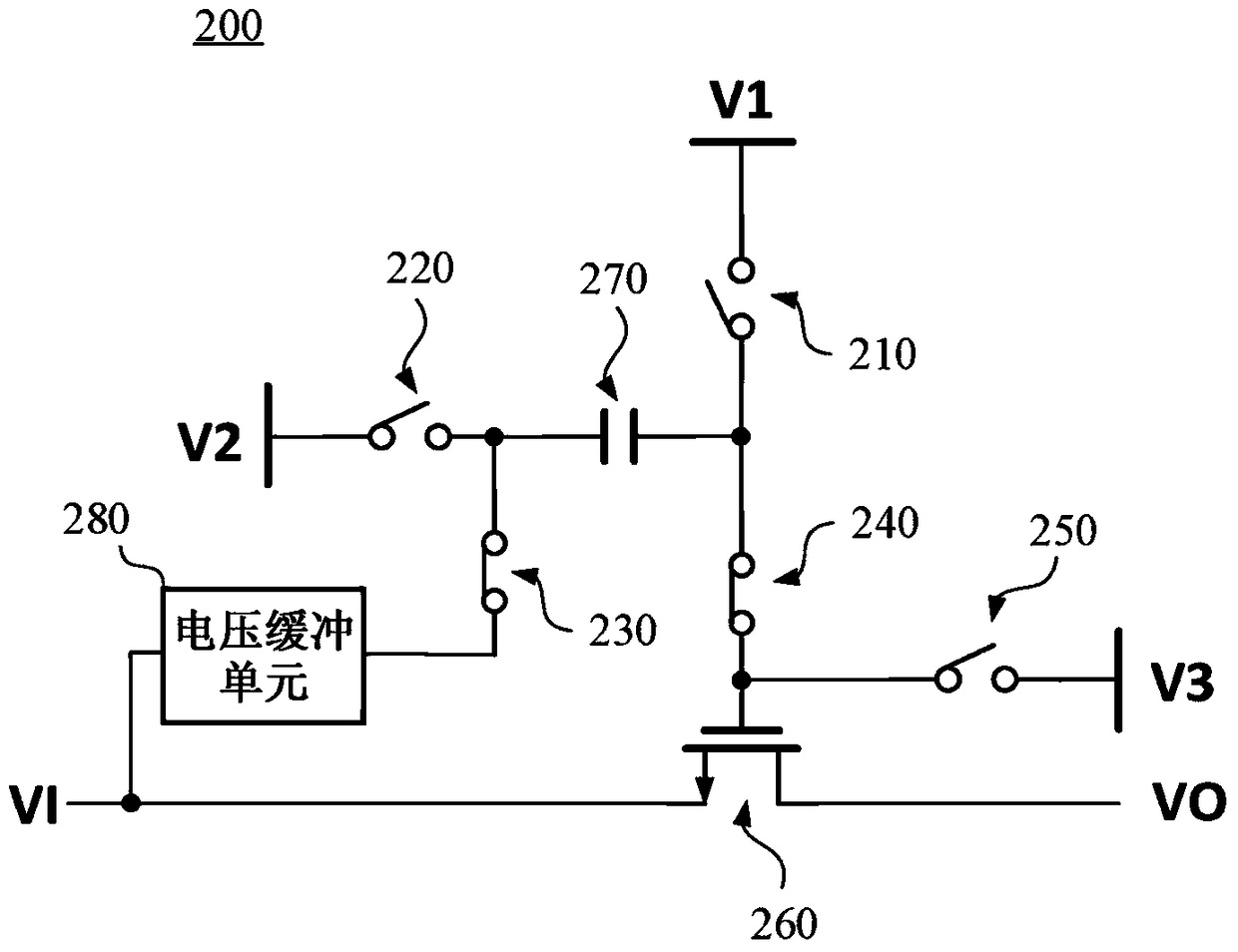
A sampling circuit used for sampling an input voltage and generating and output an output voltage. The sampling circuit includes a first switch element provided with a control terminal used for enabling the output voltage to be equal to the input voltage when the circuit is closed; a capacitor element; a second switch element coupled to a first end point and a first reference electric position; a third switch element coupled to a second end point of the capacitor element and a second reference electric position; a fourth switch element coupled to the first end point and a control terminal thereof of the capacitor; a fifth switch element coupled to the control terminal and the second reference electric position; a voltage buffering unit having large input impedance and having an input terminal coupled to the input voltage while an output terminal providing voltage equal or similar to the input voltage; and a sixth switch element coupled to the second end point of the capacitor element and an output terminal of the voltage buffering unit.

Description

technical field [0001] The present invention relates to a sampling circuit and a sampling method, in particular to a sampling circuit and a sampling method which improve the sampling accuracy and reduce the slew time of the sampling signal. Background technique [0002] see figure 1 , which is a circuit diagram of a conventional bootstrapped switch. The switching booster circuit is a common switching and sampling circuit. This circuit has been discussed in the document "Input switch configuration suitable for rail-to-rail operation of switched opamp circuits" (1999 / 01, pp.8-9) from IEEE Electronics Letters. The switching booster circuit 100 includes a switch element 110 , a switch element 120 , a switch element 130 , a switch element 140 , a switch element 150 , an N-type metal oxide semiconductor field effect transistor (hereinafter referred to as NMOS) 160 and a capacitor element 170 . The input VI and output VO of the switching boost circuit 100 are respectively couple...

Claims


Application Information

Patent Timeline
Patent Type & Authority Patents(China)
IPC IPC(8): H02M3/155
Inventor 江明澄高立龙
Owner REALTEK SEMICON CORP
Learn More