Collodion mop cleaning barrel

A collodion mop and cleaning bucket technology, applied in the field of sanitary cleaning appliances, can solve problems such as inability to squeeze water, shorten service life, and deformation of the collodion head, and achieve the effects of simple and reasonable structure, prolonging service life, and convenient operation and use

Inactive Publication Date: 2016-07-20
应高安
View PDF6 Cites 14 Cited by
  • Summary
  • Abstract
  • Description
  • Claims
  • Application Information

AI Technical Summary

Problems solved by technology

[0003] But there are the following problems in the process of use: one is that there is no device for applying extrusion force on the front and rear sides of the collodion head, and there will be water that cannot be squeezed out during use, that is, the front and rear sides are not completely squeezed or cannot be squeezed. Squeeze effect is not ideal
Second, after a certain period of use, the collodion head will be deformed, resulting in an increase in the distance between the collodion head and the water-squeezing component, and the collodion head will shake, which not only affects the water-squeezing effect, but also affects the cleaning effect and work efficiency
Third, because the pull rod assembly and the water squeeze assembly are installed on the mop rod, not only the structure of the mop is complicated, but also the strength of the mop is reduced and the service life is shortened.
Fourth, because the collodion mop does not have a matching cleaning bucket, it can only be cleaned in the sink, which is inconvenient for cleaning and dehydration
For this reason, many manufacturers and people of insight carry out research and development, but there is no relatively satisfactory product on the market so far.

Method used


Image

  • Collodion mop cleaning barrel
  • Collodion mop cleaning barrel
  • Collodion mop cleaning barrel

Examples


Embodiment Construction

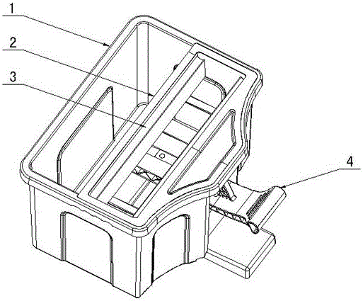
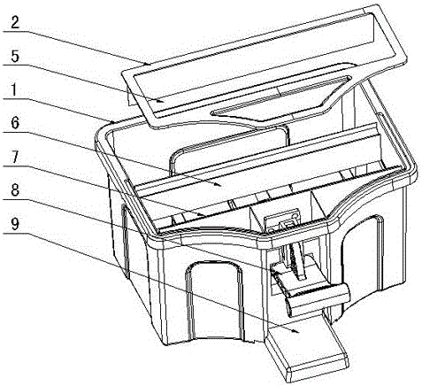
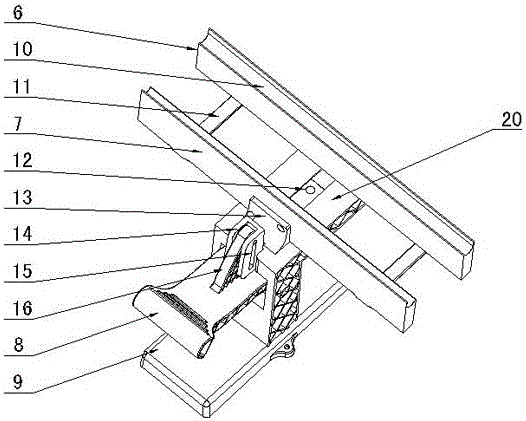
[0018] figure 1 , figure 2 , image 3 and Figure 5 Shown, for the present invention creates and adopts the concrete embodiment of the collodion mop cleaning barrel of the first kind of water squeezing scheme, it comprises the barrel body 1 that is used for collodion head cleaning, the base 9 that is fixed on the barrel body 1, described The base 9 is provided with a water squeezing device 3 and a driving device 4. The water squeezing device 3 includes a water squeezing fixed plate 7, a water squeezing movable plate 6, and a guide rail connecting rod 12. The upper part of the base 9 is provided with an expansion part 20 to expand The guide rail groove 19 is provided on the part 20, the guide rail connecting rod 12 is slidably arranged on the guide rail groove 19, the water squeezing fixed plate 7 is fixed on the expansion part 20 through the fixed plate seat 13, and the water squeezing movable plate 6 passes through the movable plate seat 18 Be fixed on the guide rail conn...


PUM


Abstract

The invention discloses a collodion mop cleaning barrel, which comprises a barrel body (1) and a base (9), wherein the base is fixed on the barrel body (1); a water extruding device (3) and a driving device (4) are arranged on the base (9); the water extruding device (3) comprises a water extruding fixing plate (7), a water extruding moving plate (6) and a guide rail connecting rod (12); the upper part of the base (9) is provided with an expanding part (20); a guide rail groove (19) is formed in the expanding part (20); a guide rail connecting rod (12) is arranged on the guide rail groove (19); the water extruding fixing plate (7) is fixed on the expanding part (20) through a fixing plate seat (13); the water extruding moving plate (6) is fixed on the guide rail connecting rod (12) through a moving plate seat (18); a collodion head is put between the water extruding fixing plate (7) and the water extruding moving plate (6) during dewatering; the driving device (4) drives the water extruding moving plate (6) to move in the direction towards the water extruding fixing plate (7) through the guide rail connecting rod (12) so that the collodion head is tightly clamped for water extrusion. After the structure is used, the collodion mop cleaning barrel has the advantages that the structure is simple and reasonable; the operation and the use are convenient; the water extruding effect is good; the work efficiency is high, and the like.

Description

technical field [0001] The invention relates to a hygienic cleaning appliance, in particular to a collodion mop cleaning bucket used in conjunction with a collodion mop. Background technique [0002] The mop is an indispensable cleaning tool in daily cleaning and sanitation. There are many kinds of it. Among them, the collodion mop can be wrung out without directly touching the collodion head with hands. It is not dirty and easy to use. It is very popular among consumers. . There are many patented technologies of collodion mop, such as the three-stage water-squeezing collodion mop disclosed by the Chinese patent, the authorized announcement number is CN201870582U. The lower end of the mop seat is connected, and the water squeeze assembly includes a connector, a pair of connecting blocks and a pair of splints. A connecting block is respectively hinged on both ends of the lower part of the mop seat. A sliding plate is hinged, the sliding plate is stacked on the bottom surfac...

Claims


Application Information

Patent Timeline
Patent Type & Authority Applications(China)
IPC IPC(8): A47L13/59
CPCA47L13/59
Inventor 应高安
Owner 应高安
Why Eureka
Try Eureka