Universal objective table for laser 3D printer

A 3D printer and stage technology, applied in the field of 3D printing, can solve the problems of inability to adjust the deflection angle, time-consuming and laborious, and influence of 3D printing effect, and achieve the effect of easy installation, easy adjustment, and enhanced stability

Active Publication Date: 2016-07-20
JIANGSU RICH OPTO TECH CO LTD
View PDF11 Cites 6 Cited by
  • Summary
  • Abstract
  • Description
  • Claims
  • Application Information

AI Technical Summary

Problems solved by technology

[0003] The rationality and optimization degree of the 3D printing optical path system directly affect the accuracy, speed and stability of printing. For example, CN104228068A discloses a rapid prototyping SLA 3D printer and its printing method. The hanging table above the vertical slot can only move up and down. , it is impossible to adjust the deflection angle according to the angle change of the resin surface in the resin tank. When the angle of the resin surface in the resin tank is inclined, the hanging platform cannot fit well with the resin surface. In order to ensure the printing effect during the printing process Best, each printing layer requires the staff to adjust the inclination angle of the hanging platform according to the angle of the resin surface, which is not only time-consuming and laborious, but also affects the 3D printing effect, and the printing accuracy, speed and product stability cannot be guaranteed at all. requirements, especially in high-end application fields such as jewelry modeling, dental molds, and prototype models, it is even more unable to meet their application requirements.

Method used


Image

  • Universal objective table for laser 3D printer
  • Universal objective table for laser 3D printer
  • Universal objective table for laser 3D printer

Examples


Embodiment Construction

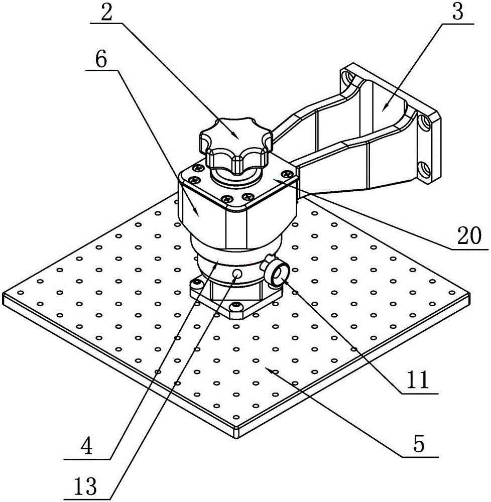
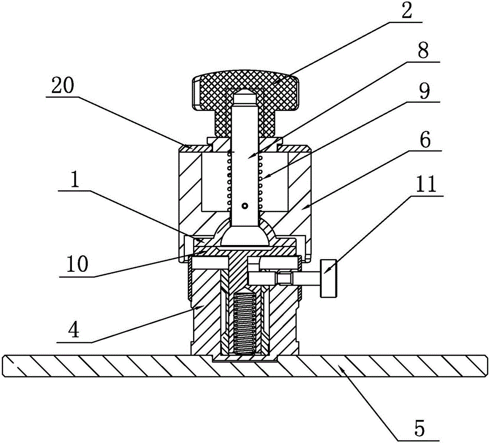
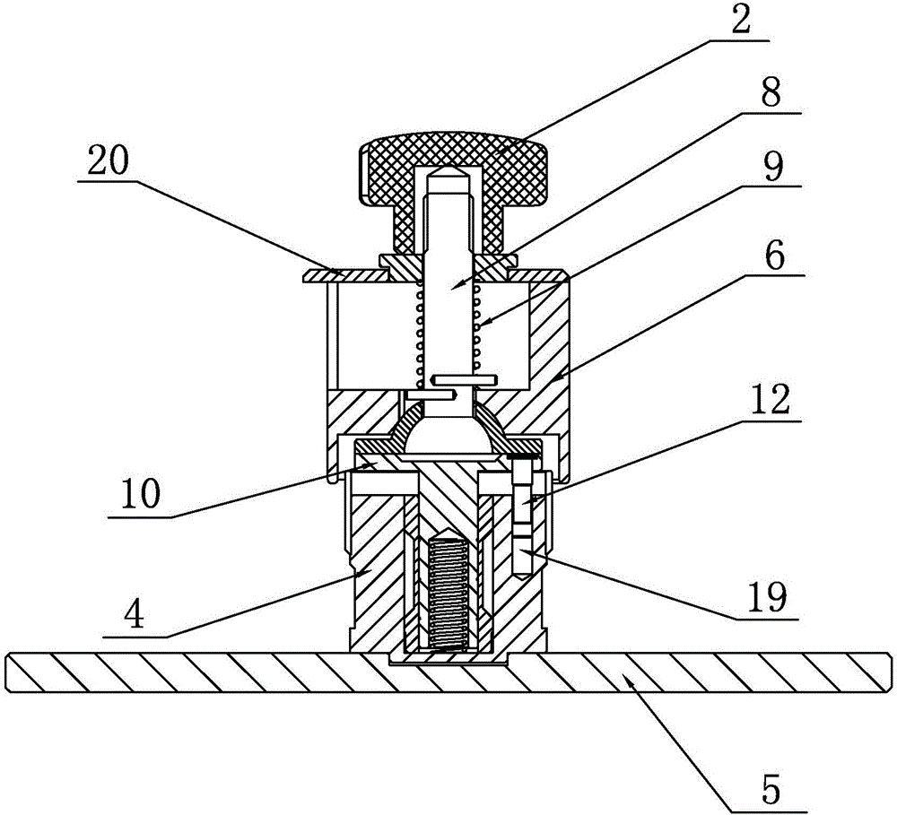
[0015] Such as figure 1 , figure 2 , image 3 As shown, it is a universal stage for a laser 3D printer of the present invention, including a knob 2, a ball screw 8, a telescopic connecting ring 1, a telescopic connecting rod 10, a protective cover 4 and a stage 5, the top of the ball screw 8 and the knob 2 The bottom end is connected by thread, and the outer side of the ball screw 8 below the knob 2 is provided with a spring 9, the outer side of the spring 9 is provided with a fixed connection sleeve 6, and a top plate 20 is arranged above the fixed connection sleeve 16, and the top of the fixed connection sleeve 16 is connected to the top plate. 20 are fixedly connected by screws between the bottom edges. The middle position of the top plate 20 is provided with a ninth through hole. The top plate 20 is sleeved on the ball screw 8 through the ninth through hole. When the end of the lifting mechanism of the 3D printer is connected, the end of the lifting mechanism of the 3D...


PUM


Abstract

The invention relates to a universal objective table for a laser 3D printer. The universal objective table is simple in structure, easy and convenient to operate and control and good in printing effect. The universal objective table comprises a rotary knob, a ball screw, a stretchable connecting ring, a stretchable connecting rod and an objective table body; the top end of the ball screw is connected with the bottom end of the rotary knob through threads, the position, below the rotary knob, of the outer side of the ball screw is sleeved with a spring, the outer side of the spring is sleeved with a fixed connecting sleeve, and the bottom end of the ball screw is provided with the stretchable connecting ring; the bottom end of the stretchable connecting ring is provided with a first hemispheric groove, a first through hole is formed in the middle position of the first groove, and the stretchable connecting ring is arranged on the ball screw in a sleeving manner through the first through hole; the outer wall of the spherical structure at the bottom end of the ball screw is in fit contact with the inner wall of the first groove, and a gap is reserved between the edge of the inner side of the first through hole and the outer wall of the ball screw; and the bottom end of the stretchable connecting ring is connected with the top end of the stretchable connecting rod, the stretchable connecting rod is connected with a protection jacket, and the bottom end of the protection jacket is connected with the top end of the objective table body placed in the horizontal direction.

Description

technical field [0001] The invention relates to the field of 3D printing, in particular to a universal stage for a laser 3D printer. Background technique [0002] Laser 3D printing is based on mathematical model files, using special wax, powdered metal or plastic and other bondable materials to construct objects by layer-by-layer printing and bonding. It is the opposite of traditional material processing, and it is a new form of three-dimensional printing that is manufactured layer by layer by adding materials. With the rapid development of 3D printing technology, with the advantages of speed and precision, laser technology as a new energy source is widely used in 3D printing, among which photosensitive resin selective curing process (SLA) occupies a dominant position in the market. SLA adopts the principle of three-dimensional engraving. The resin tank is filled with liquid photosensitive resin, and it is quickly cured under the scanning irradiation of ultraviolet laser to...

Claims


Application Information

Patent Timeline
Patent Type & Authority Applications(China)
IPC IPC(8): B29C67/00B33Y30/00
CPCB33Y30/00B29C64/227
Inventor 周双留李宝良
Owner JIANGSU RICH OPTO TECH CO LTD
Why Eureka
Try Eureka