a transmission system

A technology of transmission system and output shaft, applied in the field of transmission system, can solve the problems of inflexibility, high cost, discontinuous belt, etc., and achieve the effect of ensuring transportation quality, good load bearing and improving the scope of application

Active Publication Date: 2018-05-15
SUZHOU ITS IND TRANSFER SYST CO LTD
View PDF7 Cites 1 Cited by
  • Summary
  • Abstract
  • Description
  • Claims
  • Application Information

AI Technical Summary

Problems solved by technology

In the prior art, belts are generally used for conveying. However, when using belts for conveying, an intermediate transition mechanism is required for transition when encountering a turn, causing the belt to be discontinuous and not flexible enough.
And the weight of the product that the belt can carry is relatively light. If an iron chain is used, the cost will be higher

Method used


Image

  • a transmission system
  • a transmission system
  • a transmission system

Examples


Embodiment 1

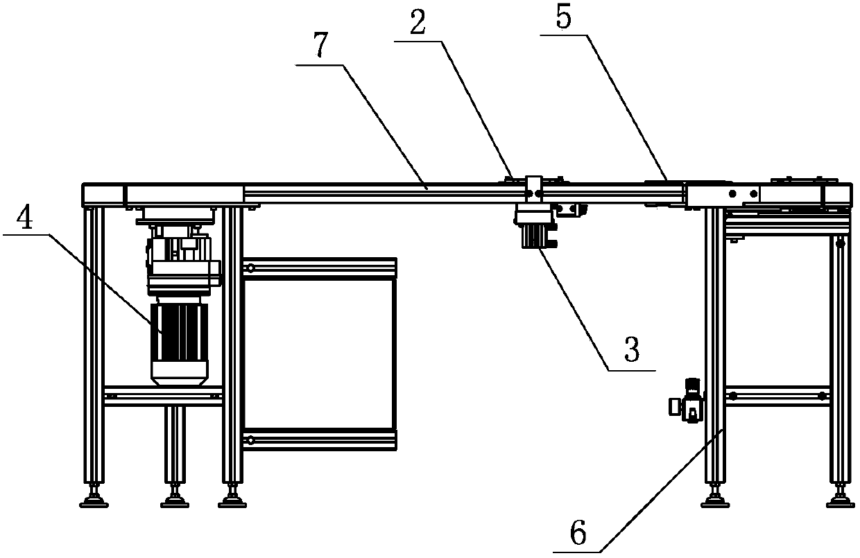
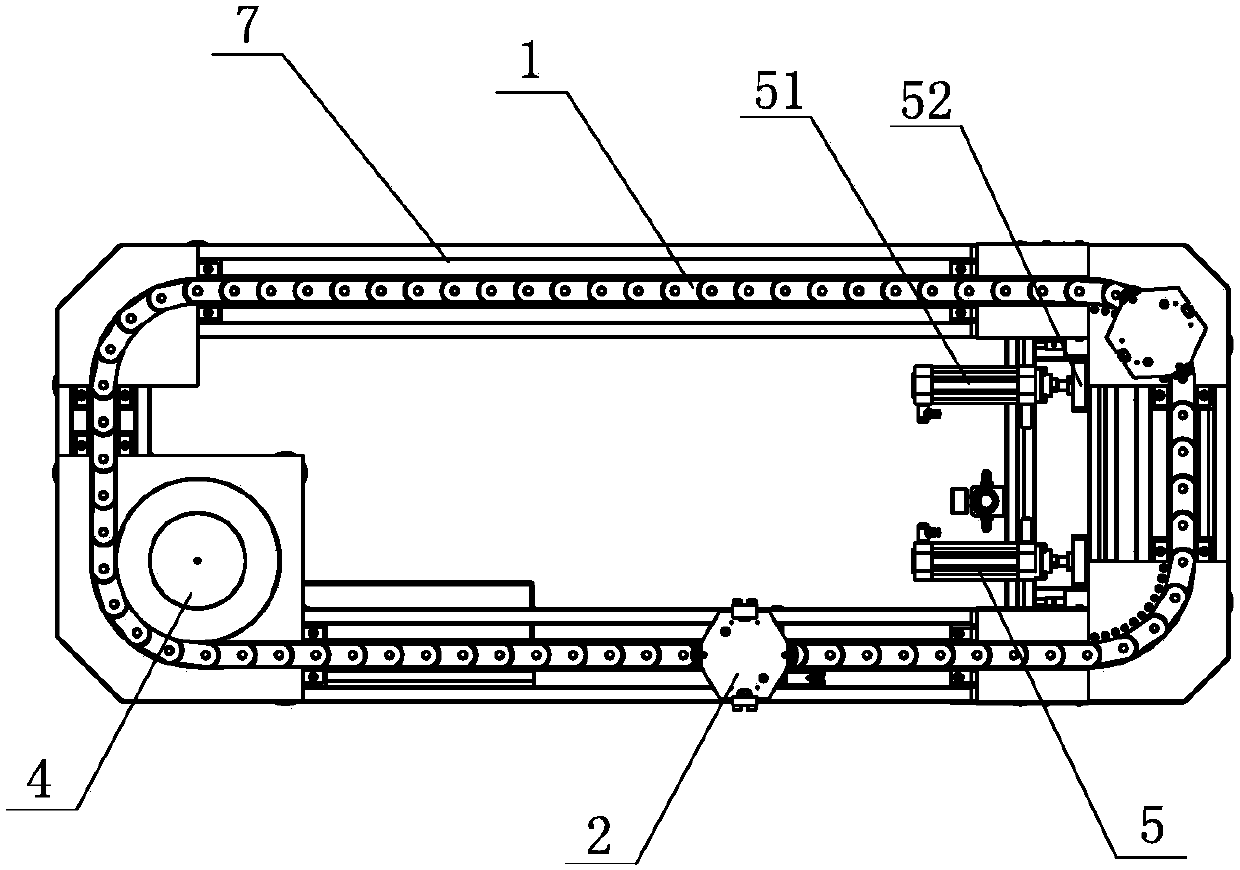
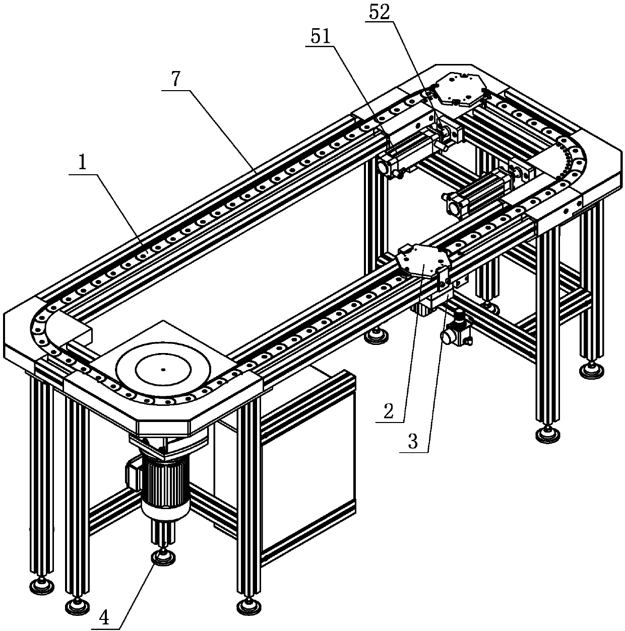
[0038] Embodiment one: see Figure 1-14 As shown, a transmission system includes a frame 6, a chain mechanism arranged on the frame 6, a driving mechanism 4, a lifting mechanism 3, a tension mechanism 5 and a tray device 2, and the chain mechanism includes 6 on the chain track 7 and the conveyor chain 1 arranged in the chain track 7, the jacking mechanism 3 is installed on the bottom of the chain track 7, the tray device 2 is arranged in the chain track 7, and the The bottom of the tray device 2 is attached to the top surface of the conveyor chain 1; the driving mechanism 4 is arranged on one side of the frame 6, and the tensioning mechanism 5 is arranged on the other side of the frame 6. On the side, the conveying chain 1 is driven by the drive mechanism 4 and the tension is adjusted by the tension mechanism 5 .

[0039] In the present invention, the product is placed in the tray device 2, and the tray device 2 is directly placed on the conveying chain 1 in the chain track 7...


PUM


Abstract

The invention discloses a transmission system. The transmission system is characterized by comprising a rack as well as a chain mechanism, a drive mechanism, a jacking mechanism, a tensioning mechanism and a tray device which are arranged on the rack, wherein the chain mechanism comprises a chain rail arranged on the rack and a conveying chain arranged in the chain rail; the jacking mechanism is mounted on the bottom of the chain rail; the tray device is arranged in the chain rail; the bottom of the tray device is adhered to the top surface of the conveying chain; the drive mechanism is arranged at one side of the rack; the tensioning mechanism is arranged at the other side of the rack; the conveying chain is driven by the drive mechanism; and the tension degree is regulated through the tensioning mechanism. The service life of the transmission system is effectively prolonged, the use cost is reduced, and the turning flexibility of the transmission system is improved.

Description

technical field [0001] The invention relates to a transmission system. Background technique [0002] Conveyor line is a widely used assembly line conveying equipment for conveying various products. In the prior art, belts are generally used for conveying. However, when using belts for conveying, an intermediate transition mechanism is required for transition when turning, resulting in discontinuous belts and insufficient flexibility. Moreover, the weight of the product that the belt can carry is relatively light, and if an iron chain is used, the cost is relatively high. Contents of the invention [0003] The purpose of the present invention is to provide a transmission system. By using this structure, the flexibility of the transmission system corner is improved, and the carrying capacity of the transmission system is also increased. [0004] In order to achieve the above object, the technical solution adopted by the present invention is: a transmission system, includin...

Claims


Application Information

Patent Timeline
Patent Type & Authority Patents(China)
IPC IPC(8): B65G17/12B65G17/38B65G21/22B65G47/88B65G23/24
CPCB65G17/12B65G17/38B65G21/22B65G23/24B65G47/8815
Inventor 许家明王永岗
Owner SUZHOU ITS IND TRANSFER SYST CO LTD
Why Eureka
Try Eureka