Double-shaft transmission type linear cutter winding device allowing horizontal locations of winding rollers to be adjustable

A horizontal position, double-shaft transmission technology, applied in the direction of winding strips, transportation and packaging, thin material processing, etc., can solve the problems of large space occupation, difficult layout of power lines, and failure to meet the use requirements, etc., to achieve switching, Realize the winding operation and prevent the effect of displacement jumping

Inactive Publication Date: 2016-07-20
CHONGQING SINSTAR PACKAGING MACHINERY
View PDF0 Cites 0 Cited by
  • Summary
  • Abstract
  • Description
  • Claims
  • Application Information

AI Technical Summary

Problems solved by technology

The drive motor Ⅱ rotates with the roller frame, so it is difficult to arrange the power cord, and during the process of the drive motor Ⅱ rotating with the roller frame, other structures cannot interfere with the drive motor Ⅱ, which takes up a lot of space. When the layout space is limited, it cannot meet the requirements. Requirements

Method used


Image

  • Double-shaft transmission type linear cutter winding device allowing horizontal locations of winding rollers to be adjustable
  • Double-shaft transmission type linear cutter winding device allowing horizontal locations of winding rollers to be adjustable
  • Double-shaft transmission type linear cutter winding device allowing horizontal locations of winding rollers to be adjustable

Examples


Embodiment Construction

[0035] The present invention will be further described below in conjunction with the accompanying drawings and specific embodiments, so that those skilled in the art can better understand the present invention and implement it, but the examples given are not intended to limit the present invention.

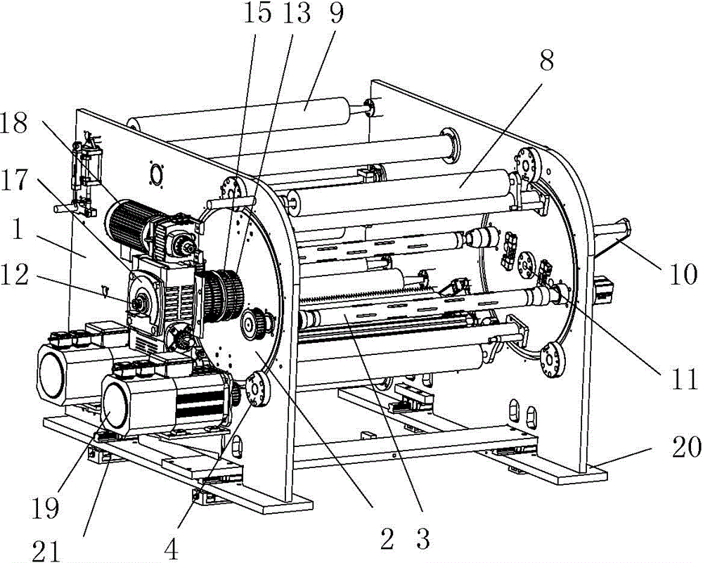
[0036] Such as figure 1 As shown, it is a structural schematic diagram of an embodiment of a double-shaft transmission type linear cutter winding device with adjustable horizontal position of the winding roller in the present invention. In this embodiment, the double-axis transmission type linear cutter rewinding device with adjustable horizontal position of the rewinding roller includes two brackets 1 located at both ends, and the two brackets 1 are correspondingly provided with coaxial mounting holes, and the mounting holes are provided with There are at least two rewinding rollers 3 that are rotatably matched to the disc-type roller frame 2 that fits in the gap between the two ...


PUM


Abstract

The invention discloses a double-shaft transmission type linear cutter winding device allowing the horizontal locations of winding rollers to be adjustable. The double-shaft transmission type linear cutter winding device comprises two supports located at the two ends. Coaxial mounting holes are formed in the two supports correspondingly. Disc-type roller stands in clearance fit with the mounting holes are arranged in the mounting holes. The winding rollers are arranged between the two disc-type roller stands. The supports are provided with rotary supporting units, and mounting bases are arranged below the two supports correspondingly. The bottom face of each mounting face is provided with a regulating base. Each regulating base comprises a bottom board and a regulating bevel board, wherein the matching faces between the bottom board and the regulating bevel board are slopes tilting relative to the axes of the winding rollers; and a regulating mechanism used for driving the bottom board to move relative to the regulating bevel board is arranged between the bottom board and the regulating bevel board. The double-shaft transmission type linear cutter winding device further comprises a drive mechanism and linear cutter mechanisms, wherein the drive mechanism is used for driving the disc-type roller stands and the two winding rollers to rotate, each linear cutter mechanism comprises a kiss-roller and cutters, and the two ends of each kiss-roller are provided with linear drive mechanisms.

Description

technical field [0001] The invention belongs to the technical field of strip winding mechanisms, and in particular relates to a double-shaft transmission linear cutter winding device with adjustable horizontal position of winding rollers. Background technique [0002] The winding mechanism is the material receiving part of the coil material processing production line. It is mainly used to mechanically wind the raw materials into coil materials. The winding mechanism is widely used in the paper roll, cloth roll, plastic roll and metal coil processing production line, and the design is diversified according to the actual process requirements. [0003] The existing winding mechanism generally includes brackets located at both ends, a roller frame is arranged between the two brackets, two winding rollers are arranged between the two roller frames, and the two roller frames are respectively rotated and mounted on the two brackets. superior. The winding of the strip can be reali...

Claims


Application Information

Patent Timeline
IPC IPC(8): B65H19/26B65H19/30B65H19/28B65H19/12B65H16/06B65H18/02B65H79/00B65H23/032B65H23/26
Inventor 陈跃华李永才其他发明人请求不公开姓名
Owner CHONGQING SINSTAR PACKAGING MACHINERY
Why Eureka
Try Eureka