Unlock instant, AI-driven research and patent intelligence for your innovation.
Simple wire winding and unwinding device applied to cable reel
What is Al technical title?
Al technical title is built by PatSnap Al team. It summarizes the technical point description of the patent document.
A technology of discharge wire and cable reel, which is applied to the field of simple retractable and discharge wire devices, can solve the problems of unstable winding work, easy winding of wires and cables out of the cable reel, etc., and achieves the effects of stable retraction and retraction, stable retraction and convenient use.
Active Publication Date: 2016-07-20
ECI HUIZHOU CABLE SCI & TECH CO LTD
View PDF9 Cites 3 Cited by
Summary
Abstract
Description
Claims
Application Information
AI Technical Summary
This helps you quickly interpret patents by identifying the three key elements:
Problems solved by technology
Method used
Benefits of technology
Problems solved by technology
However, when the existing cable reels are winding the wires and cables, the wires and cables are easy to wind out of the cable reel, making the winding work unstable and difficult to proceed.
Method used
Image
Click on the blue label to locate the original text in one second.
Reading with bidirectional positioning of images and text.
Examples
Embodiment Construction
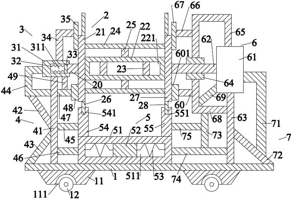
[0019] Such as figure 1 As shown, the simple receiving and discharging wire device applied to the cable reel of the present invention includes a base plate 1, a rotating device 2 located above the base plate 1, a positioning device 3 located on the left side of the rotating device 2, and a positioning device 3 located below the positioning device 3. The bracket device 4 , the counterweight device 5 located below the rotating device 2 , the motor device 6 located on the right side of the rotating device 2 and the fixing device 7 arranged on the motor device 6 .
[0020] Such as figure 1 As shown, the base plate 1 is a cuboid, and the base plate 1 is placed horizontally. The base plate 1 is provided with first support blocks 11 located on the left and right sides below, and first rollers 12 located below the first support block 11. . The first support block 11 is provided with two and is respectively located on the left and right sides below the bottom plate 1. The cross secti...
PUM
Abstract
A simple wire winding and unwinding device applied to a cable reel comprises a bottom plate, a rotating device, a positioning device, a support device, a balance weight device, a motor device and a fixing device. The bottom plate is provided with first supporting blocks and first wheels. The rotating device comprises a first vertical plate, a first roll shaft, first connecting rods, first cross rods, second connecting rods, a first ring part, a second vertical plate, a second ring part and a first fixing block. The positioning device comprises a second supporting block, first springs, a first abutting block, a first support and a first positioning block. The support device comprises a first supporting rod, a first inclined rod, a second inclined rod, a second support, a second cross rod, a third cross rod, a fourth cross rod, a second positioning block and a first vertical rod. The balance weight device comprises a balance weight frame, a balance weight block, second springs and a third supporting block. The motor device comprises a motor, a rotating shaft, a second supporting rod, a supporting ring, a third support, a fifth cross rod and a third positioning block. The simple wire winding and unwinding device can conduct stable winding and unwinding work on a wire and a cable, and winding and unwinding are stable.
Description
technical field [0001] The invention relates to the technical field of wire retraction, in particular to a simple wire retraction device applied to a cable reel. Background technique [0002] The cable reel is a reel that provides the function of winding wires and cables for enterprises in working conditions. It is currently widely used in fields such as oil fields, mines, and construction. However, when the existing cable reels are winding the wires and cables, the wires and cables are easy to wind out of the cable reel, making the winding work unstable and difficult to proceed. [0003] Therefore, it is necessary to provide a new technical solution to solve the above technical problems. Contents of the invention [0004] The object of the present invention is to provide a simple retractable wire device applied to a cable reel that can effectively solve the above-mentioned technical problems. [0005] In order to solve the above technical problems, the present invention...
Claims
Application Information
Patent Timeline
Application Date:The date an application was filed.
Publication Date:The date a patent or application was officially published.
First Publication Date:The earliest publication date of a patent with the same application number.
Issue Date:Publication date of the patent grant document.
PCT Entry Date:The Entry date of PCT National Phase.
Estimated Expiry Date:The statutory expiry date of a patent right according to the Patent Law, and it is the longest term of protection that the patent right can achieve without the termination of the patent right due to other reasons(Term extension factor has been taken into account ).
Invalid Date:Actual expiry date is based on effective date or publication date of legal transaction data of invalid patent.

