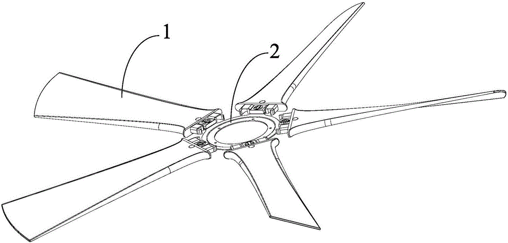
Ceiling fan blade structure and ceiling fan

A technology of fan blades and ceiling fans, applied in the field of electric fans, which can solve the problems of complicated installation structure, complicated assembly operation, and large number of ceiling fan blades

Active Publication Date: 2016-07-20
GD MIDEA ENVIRONMENT APPLIANCES MFG +1
View PDF6 Cites 4 Cited by
  • Summary
  • Abstract
  • Description
  • Claims
  • Application Information

AI Technical Summary

Problems solved by technology

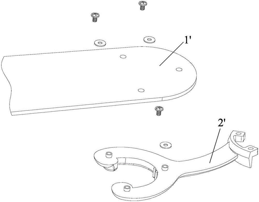
[0002] The installation structure of the ceiling fan blades currently on the market is relatively complicated, such as figure 1 and figure 2 As shown, when the fan blade 1' is assembled, the fan blade 1' needs to be installed on the connecting piece 2' first. Usually, each fan blade 1' needs to be fixed with three or more screws, and the screws and the fan blade 1' Gaskets must be installed in the space, the number of parts is large, and the cost is high. After the fan blade 1' and the connecting piece 2' are assembled, the connecting piece 2' is installed on the mounting plate (not shown in the figure). This installation structure The assembly operation is complicated, the assembly takes a long time, and the operation must be completed with the help of auxiliary tools

Method used


Image

  • Ceiling fan blade structure and ceiling fan
  • Ceiling fan blade structure and ceiling fan
  • Ceiling fan blade structure and ceiling fan

Examples


Embodiment 1

[0071] Such as Figure 5 to Figure 8As shown, the first fixing hole 1121 and the second fixing hole 2121 are non-circular holes; the fixing member is a fixing pin 3, and the fixing pin 3 includes an integrally formed first limiting portion 31, a connecting portion 32 and the second limiting portion 33, the first limiting portion 31 is non-circular; wherein, when assembling, first place the first limiting portion 31 and the first fixing hole 1121 or the second The relative angle of the fixing hole 2121 is controlled within the first preset range. At this time, the first limiting part 31 can be passed through the first fixing hole 1121 and the second fixing hole 2121, and then the fixing hole 2121 can be rotated. The pin 3 controls the relative angle between the first limiting portion 31 and the first fixing hole 1121 or the second fixing hole 2121 within a second preset range. At this time, the first limiting portion 31 and the One of the second limiting portions 33 interferes...

Embodiment 2

[0075] Embodiment two (not shown in the figure):

[0076] The fixing member is a screw; wherein, the stem of the screw can pass through the first fixing hole and the second fixing hole and be screwed with a nut. After the screw is installed, the head of the screw and the nut in the One interferes with the fan blade, and the other of the head of the screw and the nut interferes with the mounting plate, so as to fix the first socket part and the second socket part.

Embodiment 3

[0077] Embodiment three (not shown in the figure):

[0078] The fixing member is a screw; wherein, the first fixing hole and / or the second fixing hole is a screw hole, and the rod of the screw can be screwed into the screw hole. After the screw is installed, the screw's The head is in conflict with the fan blade or the mounting plate, and the fixing hole on the other of the fan blade or the mounting plate must be a screw hole, and the shank of the screw is screwed into it, so as to connect the first socket part and the second socket. The two socket parts are fixed.


PUM


Abstract

The invention provides a ceiling fan blade structure and a ceiling fan. The ceiling fan blade structure comprises at least one fan blade and a mounting plate; first inserting parts are arranged on the fan blades, and second inserting parts are arranged on the mounting plate; the mounting plate and the fan blades can be detachably connected through cooperation of the first inserting parts and the second inserting part; and according to the scheme, the mounting manner of the fan blades is changed, connecting parts used in an existing fan blade assembly scheme are removed, the first inserting parts are arranged on the fan blades, the second inserting parts are arranged on the mounting plate, and through corresponding inserting of the first inserting parts and the second inserting parts, assembling of the fan blades and the mounting plate can be rapidly completed; and due to design, the number of parts of the ceiling fan blade structure is small, the cost is low, when the fan blades are assembled, assembling operation can be completed without assistance of auxiliary tools, assembly operation is simple, and spent time is short.

Description

technical field [0001] The invention relates to the field of electric fans, more specifically, to a ceiling fan blade structure and a ceiling fan with the ceiling fan blade structure. Background technique [0002] The installation structure of the ceiling fan blades currently on the market is relatively complicated, such as figure 1 and figure 2 As shown, when the fan blade 1' is assembled, the fan blade 1' needs to be installed on the connecting piece 2' first. Usually, each fan blade 1' needs to be fixed with three or more screws, and the screws and the fan blade 1' Gaskets need to be installed in between, the number of parts is large, and the cost is high. After the fan blade 1' and the connecting piece 2' are assembled, the connecting piece 2' is installed on the mounting plate (not shown in the figure). This installation structure The assembly operation is complicated, the assembly takes a long time, and the operation must be completed with the help of auxiliary tool...

Claims


Application Information

Patent Timeline
Patent Type & Authority Applications(China)
IPC IPC(8): F04D29/34
CPCF04D29/34
Inventor 唐新民雷水生梁耀光
Owner GD MIDEA ENVIRONMENT APPLIANCES MFG
Why Eureka
Try Eureka