
Driving belt auxiliary extrusion conical disk belt-type variable transmission

A technology of speed change device and transmission belt, applied in the field of transmission speed change, can solve problems such as affecting the life of steel belt, affecting transmission efficiency and transmission capacity, and being easy to slip.

Inactive Publication Date: 2016-07-20
钟晓悦
View PDF4 Cites 3 Cited by
  • Summary
  • Abstract
  • Description
  • Claims
  • Application Information

AI Technical Summary

Problems solved by technology

[0002] Ordinary conical disc steel belt continuously variable transmission (CVT), there is no additional extrusion force on the steel belt in the contact section with the conical disc, and it is easy to slip between the conical disc and the steel belt, which not only affects the transmission efficiency and transmission capacity, but also affects the life of the steel belt

Method used


Image

  • Driving belt auxiliary extrusion conical disk belt-type variable transmission
  • Driving belt auxiliary extrusion conical disk belt-type variable transmission
  • Driving belt auxiliary extrusion conical disk belt-type variable transmission

Examples


Embodiment Construction

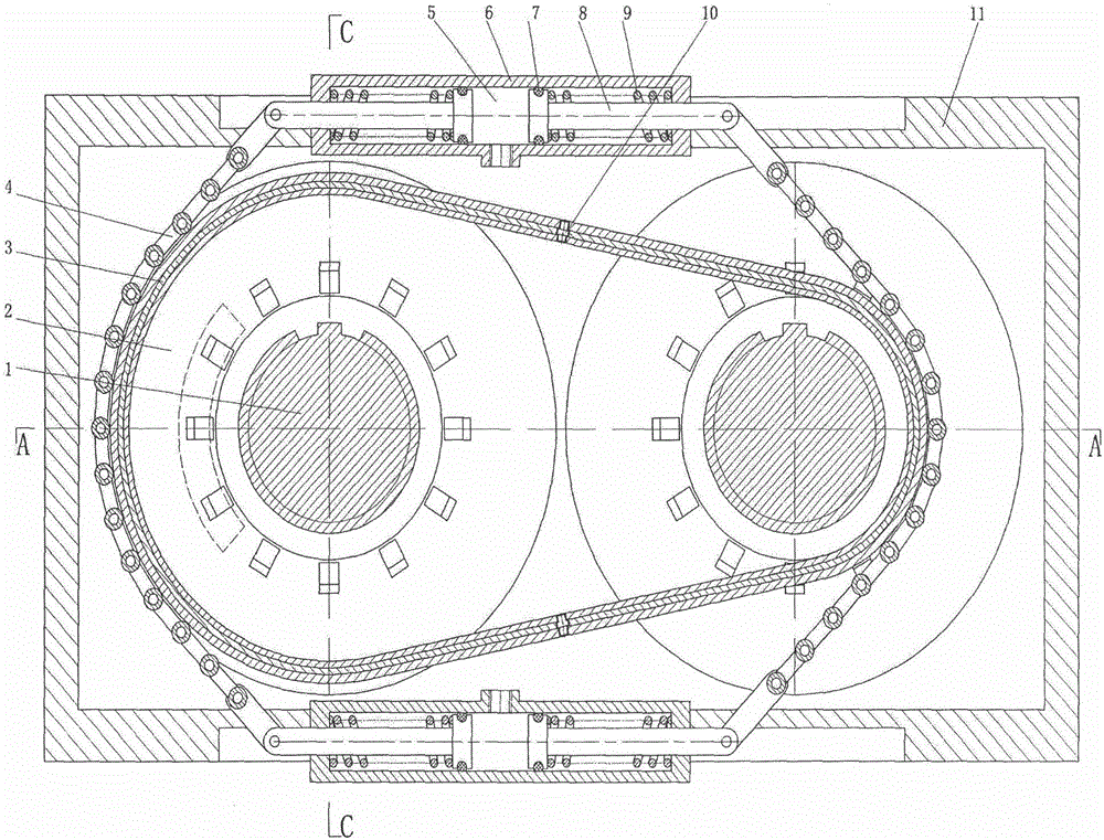
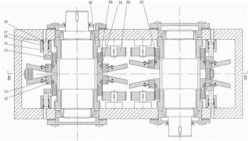
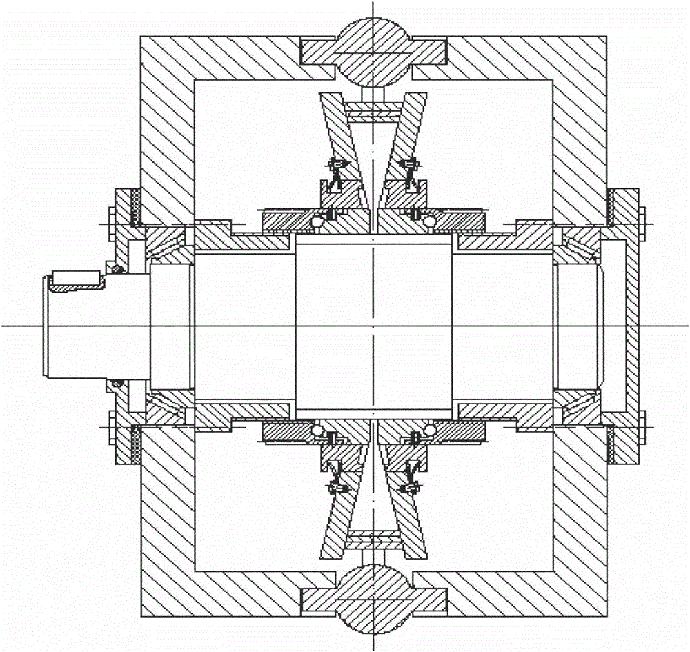
[0014] The basic scheme of the patent of the present invention is to set a back force mechanism on the outer back side of the drive belt of the conical-disk-belt type transmission and the conical-disk contact section or set a side force mechanism on both sides to limit the relative sliding between the drive belt and the conical-disk cone surface; The transmission belt is clamped between two sliding cones on the same spline shaft and arranged opposite to each other, and connects two sets of cones; under the action of the movement control mechanism of the cones, with the movement of the coaxial cones, the transmission belt will move between the cones The diameter of the tapered surface can be reduced, and the transmission ratio can be changed continuously or at a fixed value. In order to clearly illustrate the technical features of this solution, the following describes this solution through specific implementation modes and in conjunction with the accompanying drawings.

[0015...


PUM


Abstract

The invention belongs to the technical field of driving variable transmission and discloses a driving belt auxiliary extrusion conical disk belt-type variable transmission. The driving belt auxiliary extrusion conical disk belt-type variable transmission comprises spline shafts, conical disks, a driving belt, conical disk displacement control sleeves, support sleeves, servo motor shaft gears, stress application chains, double-piston tensioning assemblies, callipers, double ring tooth-shaped positioning springs, arc pressure block assemblies, a carriage body and the like. The driving belt auxiliary extrusion conical disk belt-type variable transmission is characterized in that back stress application mechanisms are arranged on the outer back surfaces of the driving belt at conical disk contact sections, or side stress application mechanisms are arranged on two side surfaces of the driving belt at conical disk contact sections, so that relative sliding between the driving belt and conical surfaces of the conical disks is limited; the driving belt is clamped between two sliding conical disks which are oppositely arranged on the same spline shaft, and is connected with the two groups of conical disks; and under the action of conical disk movement control mechanisms, along with the moving of the coaxial conical disks, the diving belt is reduced on the conical surfaces of the conical disks, so that the transmission ratio can be changed in a continuous manner or in a constant-value manner. By adopting the driving belt auxiliary extrusion conical disk belt-type variable transmission, the transmission efficiency and driving capacity of an ordinary conical disk steel belt variable transmission can be improved; power transmission can be cut off or connected through stress application mechanisms and conical disk control systems; and the driving belt auxiliary extrusion conical disk belt-type variable transmission can also be combined with other variable transmissions for use.

Description

technical field [0001] The patent of the present invention belongs to the technical field of transmission and speed change. Background technique [0002] Ordinary conical disc steel belt continuously variable transmission (CVT), there is no additional extrusion force on the steel belt in the contact section with the conical disc, and it is easy to slip between the conical disc and the steel belt, which not only affects the transmission efficiency and transmission capacity, but also affects the life of the steel belt . [0003] The patent of the present invention applies additional extrusion force to the outer back side or both sides of the transmission belt of the cone-disc contact section to reduce the slipping phenomenon between the cone-disc and the transmission belt, which can not only improve the transmission efficiency and transmission capacity, but also can pass the force mechanism and the cone The disc control system cuts or engages power transmission and can also b...

Claims


Application Information

Patent Timeline
IPC IPC(8): F16H9/24
CPCF16H7/08F16H9/24
Inventor 钟晓悦
Owner 钟晓悦
Learn More