
A mimo radar imaging method under the condition of array element failure

A technology of radar imaging and array elements, which is applied in the directions of radio wave reflection/re-radiation, utilization of re-radiation, measurement devices, etc., and can solve problems affecting the quality of MIMO radar imaging, etc.

Active Publication Date: 2018-02-02
NANJING UNIV OF INFORMATION SCI & TECH
View PDF8 Cites 0 Cited by
  • Summary
  • Abstract
  • Description
  • Claims
  • Application Information

AI Technical Summary

Problems solved by technology

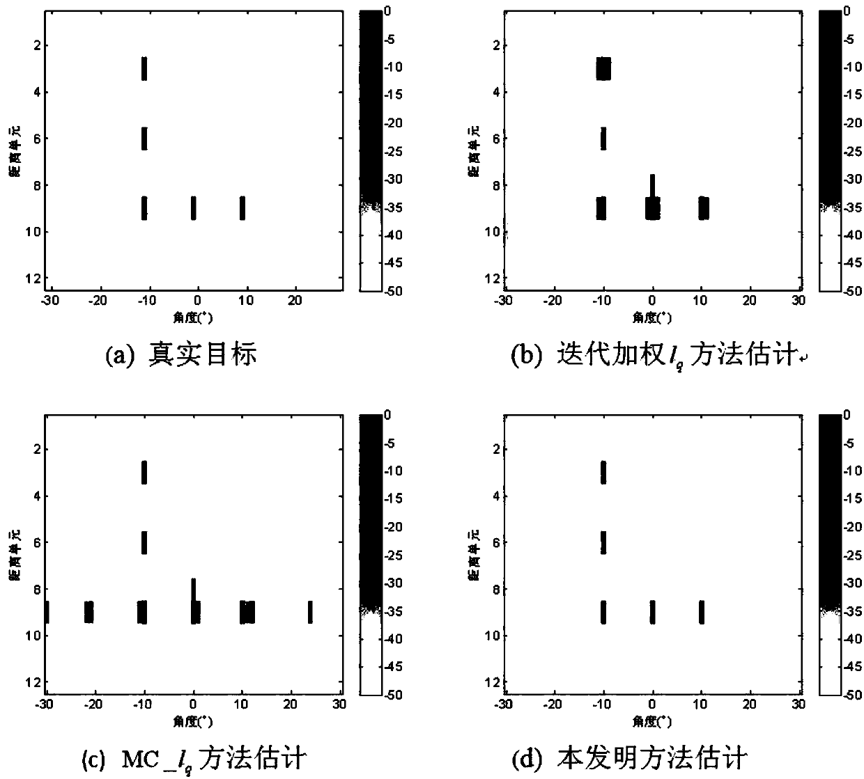
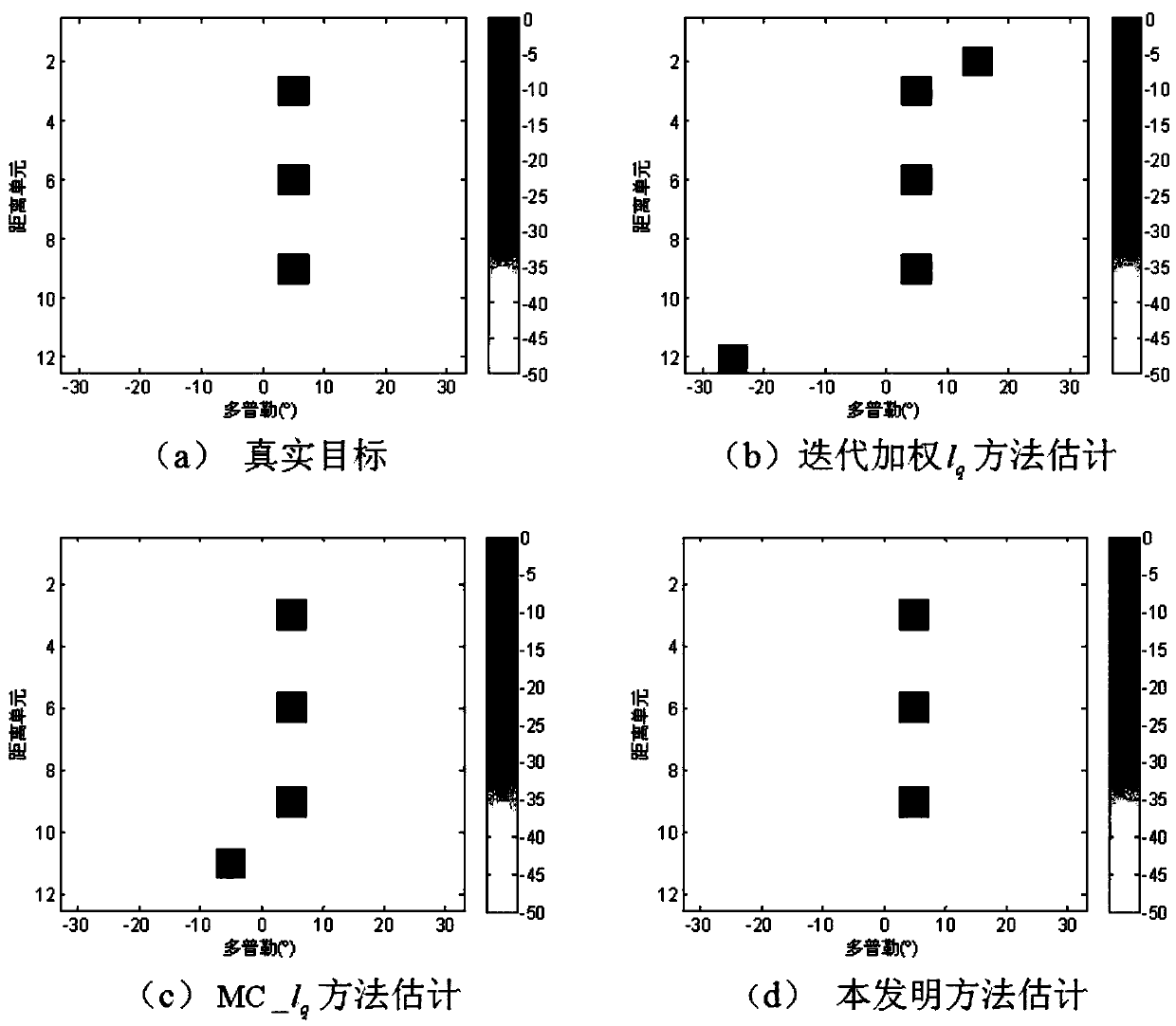
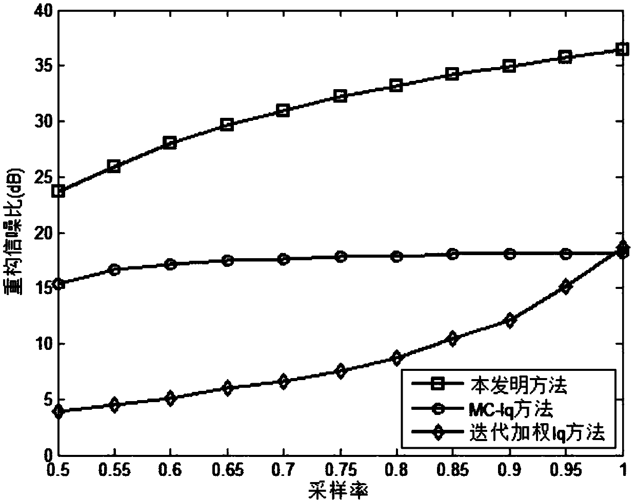
[0010] Purpose: In view of the failure of the receiving array element in the MIMO radar, due to the missing of the entire row of data in the sampling data matrix, that is, the entire row of elements is zero, which leads to the failure of matrix filling and affects the imaging quality of the MIMO radar. The present invention provides a MIMO radar imaging method under the condition of array element failure

Method used


Image

  • A mimo radar imaging method under the condition of array element failure
  • A mimo radar imaging method under the condition of array element failure
  • A mimo radar imaging method under the condition of array element failure

Examples


Embodiment Construction

[0026] The present invention will be further described below in conjunction with the accompanying drawings.

[0027] A MIMO radar imaging method under the condition of array element failure,

[0028] Step 1: Establish a non-uniform sampling MIMO radar echo signal model under the failure of the array element;

[0029] 1a. Assume that the centralized MIMO radar has M t transmit antennas and M r receiving antennas, M t The transmit signal waveform matrix of an antenna is

[0030]

[0031] where x m =[x m (1), x m (2),...,x m (L)] T Represents the transmitted signal of the mth transmitting antenna; L is the length of the transmitted signal;

[0032] 1b. Divide the target scene area into P distance units, K angle units and H Doppler units; then the target scene area is divided into D discrete distance-angle-Doppler units {(τ p ,θ k ,ω h )}, D=P K H, where 1≤p≤P, 1≤k≤K, 1≤h≤H;

[0033] 1c. Suppose the h-th Doppler unit is denoted as ω h , then define the signal corres...


PUM


Abstract

The invention discloses an MIMO radar imaging method on condition of array element failure. A fine random disturbance amount which obeys Gaussian distribution is superposed on a line element that corresponds with a failure array element position in an MIMO radar echo signal matrix. Matrix filling technology can be used for recovering a non-uniform sampled MIMO radar echo data matrix to a complete uniform sampling data matrix. Then an iterative weighting lq least method is used for estimating an objective scene vector. Because the echo data of the failed array element are not effectively utilized, a relatively large error exists in the reconstructed objective scene, thereby reducing the imaging quality of the object. For further improving the reconstruction precision of the objective scene vector, lost object receiving data of the failure array element are reconstructed by means of the coarse estimated value of the objective scene vector and a perception matrix. Then a matrix filling method and an iterative weighting lq least method are utilized for obtaining a high-precision objective scene vector estimated value, thereby settling an MIMO radar imaging problem on condition of array element failure.

Description

technical field [0001] The invention relates to a MIMO radar imaging method under the condition of array element failure, and belongs to the technical field of MIMO radar imaging. Background technique [0002] As a new system radar technology, MIMO (Multiple Input Multiple Output) radar has been highly concerned and researched by researchers recently. Compared with traditional phased array radar, MIMO radar can significantly improve the identification ability and angular resolution of parameters, and improve the flexibility of beam design; it has better target detection performance and parameter estimation performance; the array aperture is expanded through virtual antenna , to increase the upper limit of the number of targets that can be recognized. [0003] Target imaging has become one of the important branches in the development of MIMO radar systems. In recent years, compressed sensing (CS) theory has been widely used in MIMO radar target imaging. Compressed sensing ...

Claims


Application Information

Patent Timeline
Patent Type & Authority Patents(China)
IPC IPC(8): G01S13/89
CPCG01S13/89
Inventor 陈金立周运李家强
Owner NANJING UNIV OF INFORMATION SCI & TECH
Learn More