
A print quality detection device

A technology for detection devices and printed products, applied in measuring devices, material analysis through optical means, instruments, etc., can solve problems such as high false positives, pollution, and affecting the accuracy and accuracy of face quality detection, and achieve improved stability, The effect of reducing the false positive rate

Active Publication Date: 2018-04-06
CHENGDU BANKNOTE PRINTING
View PDF2 Cites 0 Cited by
  • Summary
  • Abstract
  • Description
  • Claims
  • Application Information

AI Technical Summary

Problems solved by technology

[0003] At present, the detection device for the quality of printed products is usually installed at the corresponding position of the impression cylinder, and the imaging effect obtained at this position is smooth and stable. However, in the existing two-color printers, especially the M97 two-color printers, Since there are many beams in front of the impression cylinder, the installation position of the detection system is limited, and the detection camera and light source cannot be installed in the printing department, and the image is formed at the impression cylinder. Since the imaging unit is close to the impression cylinder, printing ink and dust are easy to touch the camera. The lens and light source cause serious pollution, which leads to uneven brightness and darkness of the collected image, which seriously affects the precision and accuracy of face quality detection
At present, the printed product inspection of the M97 two-color printer in the industry adopts the imaging method at the paper delivery section, which has the disadvantages of large paper jitter, unstable imaging, and high false alarms.

Method used


Image

  • A print quality detection device
  • A print quality detection device
  • A print quality detection device

Examples


Embodiment Construction

[0015] Below in conjunction with accompanying drawing, the present invention is described in detail.

[0016] In order to make the object, technical solution and advantages of the present invention more clear, the present invention will be further described in detail below in conjunction with the accompanying drawings and embodiments. It should be understood that the specific embodiments described here are only used to explain the present invention, not to limit the present invention.

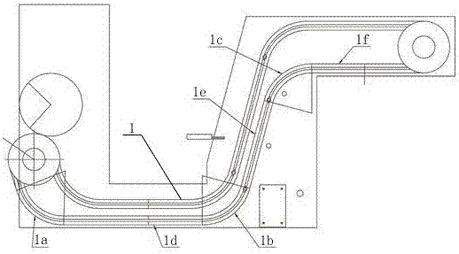
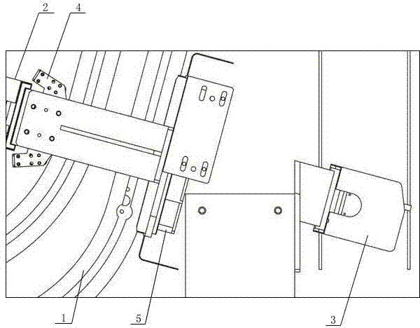
[0017] Such as image 3 with 4 As shown, a print quality detection device, the detection device is arranged at the corresponding position of the chain 1 of the two-color printer to form a detection point for the print quality, and the detection device includes a camera composition 2, a perspective camera 3, and a light source 4 And suction flattening device 5, such as figure 1 As shown, the chain 1 is composed of a first arc segment 1a, a second arc segment 1b, a third arc segment 1c, a firs...


PUM

PropertyMeasurementUnit
diameteraaaaaaaaaa

Abstract

The invention discloses a printed matter quality test device. The test device is arranged at a position corresponding to a chain of a bi-color ink recorder for forming a test point for the quality of printed matter, the test device comprises a camera assembly, a perspective camera, a light source and an air-drafting and flattening device, the chain is composed of a first arc segment, a second arc segment, a third arc segment, a first straight-line segment, a second straight-line segment and a third straight-line segment, the test point is arranged at a climbing position corresponding to the second straight-line segment of the chain, the camera assembly and the air-drafting and flattening device are arranged at the two sides of the chain corresponding to the test point respectively, the light source and the camera assembly are arranged at the same side, and the perspective camera and the air-drafting and flattening device are arranged at the same side. According to the printed matter quality test device, the test point is arranged at the position corresponding to the chain of the bi-color ink recorder, the imaging problem that in an existing bi-color ink recorder, a test device cannot be arranged at the position of an impression cylinder but is arranged on a collection portion is effectively solved, imaging stability is greatly improved, and the false alarm rate is lowered.

Description

technical field [0001] The invention belongs to the technical field of print quality detection, and in particular relates to a print quality detection device mainly used for a two-color printer. Background technique [0002] With the development of computer science, machine vision technology has played an increasingly important role in the printing industry as a new quality control method. The online print quality inspection system uses machine vision as the core technology, which can effectively monitor and control the print production process. Imaging is the most important part of the inspection system, and it is also a crucial content in the design of the machine inspection system. The requirements for image deformation, flatness, and clarity should be improved as much as possible, and favorable conditions can be provided for image software processing. [0003] At present, the detection device for the quality of printed products is usually installed at the corresponding ...

Claims


Application Information

Patent Timeline
Patent Type & Authority Patents(China)
IPC IPC(8): G01N21/898
Inventor 舒粤胡新玥夏小东马可刘军汪雄张洋
Owner CHENGDU BANKNOTE PRINTING
Learn More