Communication equipment wiring rack

A communication equipment and cable routing technology, which is applied in the direction of fiber mechanical structure, etc., can solve the problems of low communication performance of equipment, substandard bending radius, and easy damage of cables.

Inactive Publication Date: 2016-07-20
HANGZHOU HUAWEI DIGITAL TECH
View PDF6 Cites 0 Cited by
  • Summary
  • Abstract
  • Description
  • Claims
  • Application Information

AI Technical Summary

Problems solved by technology

[0003] In the above-mentioned technology, the cable will reserve a lengthy section, and it will not be fixed, so when the upper shell and the lower shell are opened or closed, the cable is likely to be clamped, resulting in damage to the cable
In addition, because the cables between the upper shell and the lower shell are only bundled with sleeves, the bending path and radius of the cables are uncontrollable, and the bending radius of the cables containing optical fibers is likely to be substandard. , thus affecting the communication performance of the device
It can be seen that in the above technology, the cables connected between the upper shell and the lower shell are easily damaged, and the communication performance of the device is not high

Method used


Image

  • Communication equipment wiring rack
  • Communication equipment wiring rack
  • Communication equipment wiring rack

Examples


Embodiment Construction

[0030] The following will clearly and completely describe the technical solutions in the embodiments of the present invention with reference to the accompanying drawings in the embodiments of the present invention. Obviously, the described embodiments are only some, not all, embodiments of the present invention. Based on the embodiments of the present invention, all other embodiments obtained by persons of ordinary skill in the art without creative efforts fall within the protection scope of the present invention.

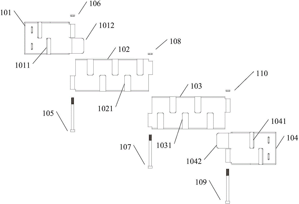
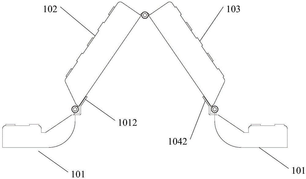
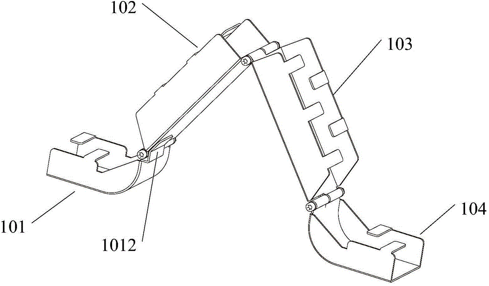
[0031] figure 1 It is a schematic structural diagram of a cable rack for communication equipment provided by an embodiment of the present invention, as shown in figure 1 shown, including:

[0032] The first bracket 101 of the groove structure, at least one wire harness tongue 1011 is provided on the notch of the groove structure of the first bracket 101, and the bottom of the groove structure of the first bracket 101 is fixedly connected to the upper shell of the ...


PUM


Abstract

The embodiment of the invention discloses a communication equipment wiring rack. The communication equipment wiring rack is characterized in that the communication equipment wiring rack comprises a first bracket of a groove-type structure; the gap of the groove-type structure of the first bracket is provided with at least one wire bunching tongue piece; the head end of the first bracket is movably connected with the first end of a second bracket of a groove-type structure; the head end of the first bracket is provided with a first limiting tongue piece which extends outwards; the gap of the groove-type structure of the second bracket is provided with at least one wire bunching tongue piece; the second end of the second bracket is movably connected with the first end of a third bracket of a groove-type structure; the gap of the groove-type structure of the third bracket is provided with at least one wire bunching tongue piece; and the communication equipment wiring rack also comprises a fourth bracket of a groove-type structure; the gap of the groove-type structure of the fourth bracket is provided with at least one wire bunching tongue piece; the head end of the fourth bracket is movably connected with the second end of the third bracket; and the head end of the fourth bracket is provided with a second limiting tongue piece which extends outwards. With the communication equipment wiring rack provided by the embodiments of the invention adopted, a cable between an upper shell and a lower shell can be prevented from being damaged, and the performance of communication equipment can be improved.

Description

technical field [0001] The invention relates to the field of communications, in particular to a cable rack for communications equipment. Background technique [0002] At present, there are many integrated communication devices, and these devices are divided into an upper case and a lower case, and the upper case and the lower case are connected by a hinge or a rotating shaft. With the development of communication technology, the modularization program inside the communication equipment is getting higher and higher. Due to the limited space of the communication equipment, the communication equipment will be equipped with modules in the upper shell and the lower shell, and the modules between the upper shell and the lower shell Connect via various cables. In practical applications, it is often necessary to open or close the upper case and the lower case during installation and maintenance of communication equipment. In order to prevent the cables between the upper case and th...

Claims


Application Information

Patent Timeline
Patent Type & Authority Applications(China)
IPC IPC(8): G02B6/44
Inventor 蒋方荣
Owner HANGZHOU HUAWEI DIGITAL TECH
Why Eureka
Try Eureka