
3D display method and system

A display system, 3D technology, applied in stereo systems, image communication, electrical components, etc., can solve the problem that the viewer cannot be guaranteed to be in a stable left-eye field of view and right-eye field of view, and the 3D viewing effect cannot be achieved.

Active Publication Date: 2016-07-20
BOE TECH GRP CO LTD +1
View PDF7 Cites 9 Cited by
  • Summary
  • Abstract
  • Description
  • Claims
  • Application Information

AI Technical Summary

Problems solved by technology

[0004] However, the current 3D display technology can only perform 3D display when the relative position between the viewer and the display is fixed, and when the relative movement between the viewer and the display is carried out, for example, passengers on the subway watch the two sides of the subway. When the advertising display board, the viewpoints of the left and right eyes change rapidly, and it is impossible to ensure that the viewer is in a stable left and right eye field of view, and thus cannot achieve a 3D viewing effect in a moving state

Method used


Image

  • 3D display method and system
  • 3D display method and system
  • 3D display method and system

Examples


Embodiment Construction

[0043] The following will clearly and completely describe the technical solutions in the embodiments of the present invention with reference to the accompanying drawings in the embodiments of the present invention. Obviously, the described embodiments are only some, not all, embodiments of the present invention.

[0044] In addition, the terms "first" and "second" are used for descriptive purposes only, and cannot be understood as indicating or implying relative importance or implicitly specifying the quantity of indicated technical features. Thus, a feature defined as "first" and "second" may explicitly or implicitly include one or more of these features. In the description of the present invention, unless otherwise specified, "plurality" means two or more.

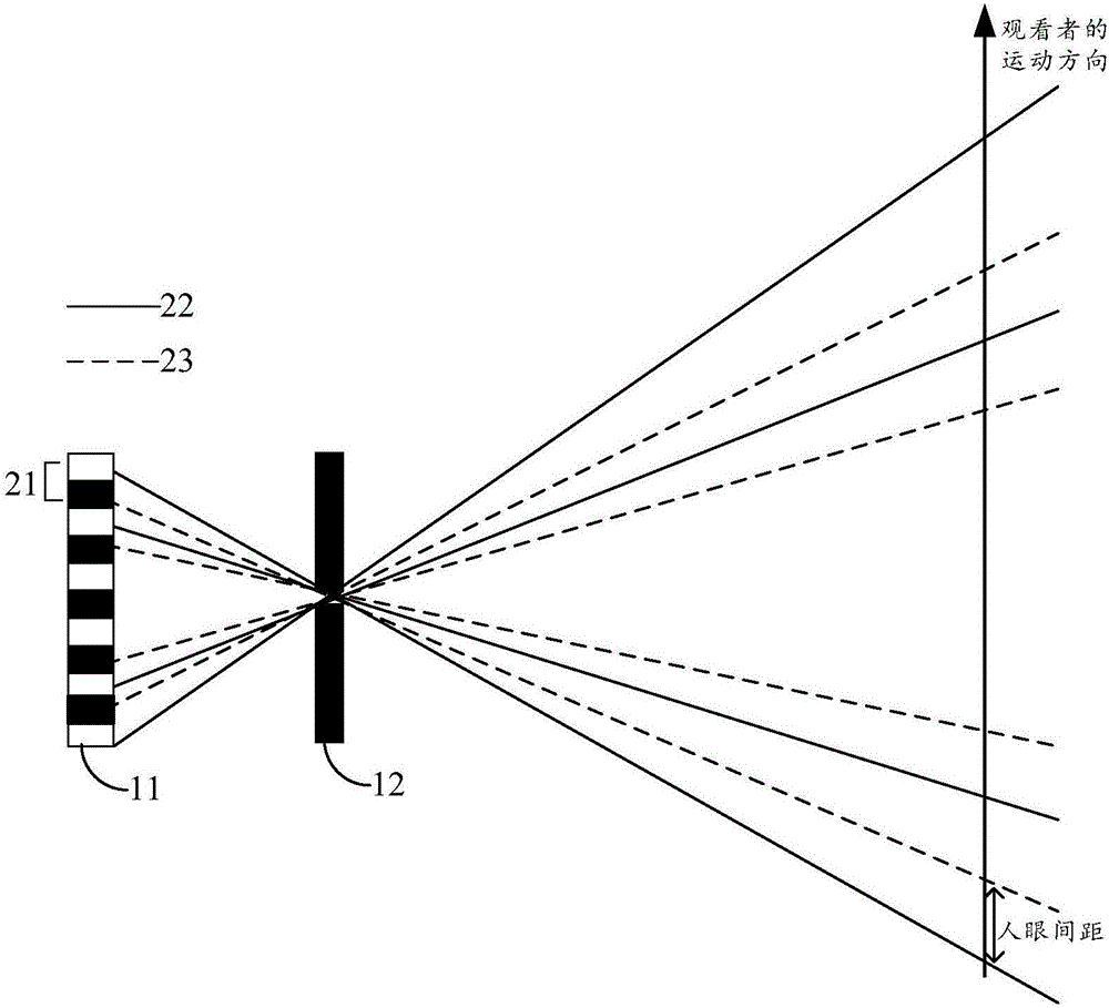
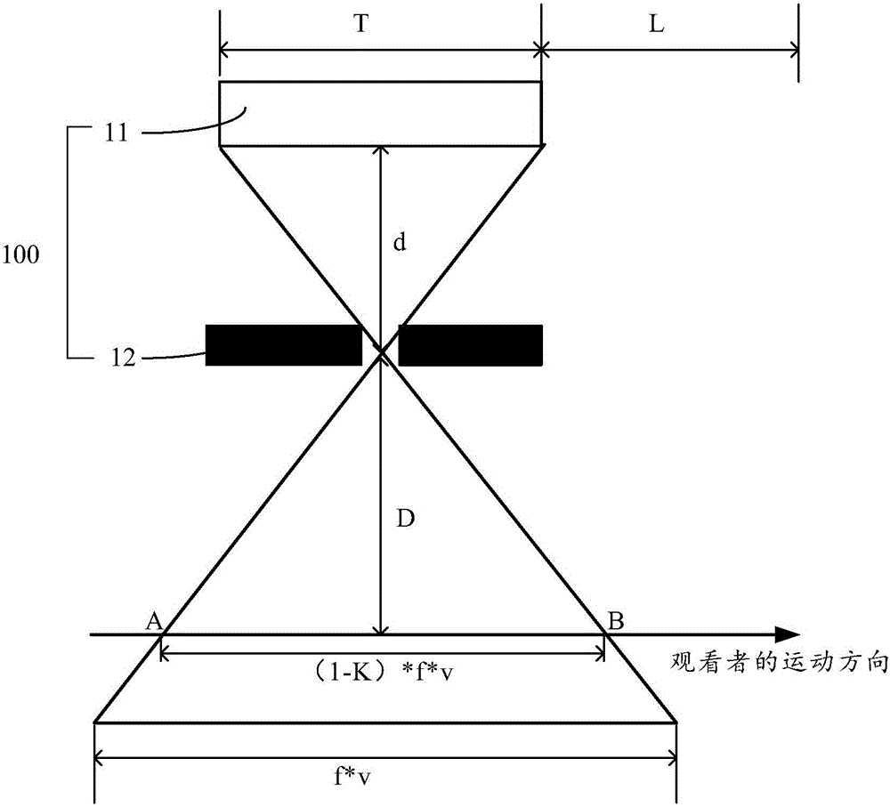
[0045] Embodiments of the present invention provide a 3D display system, such as figure 1 As shown, the 3D display system specifically includes N display devices 100 arranged sequentially along the movement direction of...


PUM


Abstract

The embodiment of the invention, which relates to the display field, provides a 3D display method and system. When a watcher moves relative to a display device, the watcher can watch a stable 3D pattern during the relative movement process. The system comprises N display devices arranged successively along the moving direction of the watcher, wherein the display devices include 3D display panels and slit devices that are arranged at light-emitting sides of the 3D display panel and are opposite to the 3D display panels. The distances between the 3D display panels and the slits of the slit devices are d and the distances between the watcher and the slits of the slit devices are D; and the d and D meet the following formula: d / D= T / (T+L)*(1-K), wherein the T expresses widths of the 3D display panels along the moving direction of the watcher, the L expresses the distances between the adjacent display devices, and the K expresses black frame insertion proportions of all frames in the 3D display panels. The method can be applied to a 3D display process.

Description

technical field [0001] The present invention relates to the field of display technology, in particular to a 3D display method and system. Background technique [0002] The principle of 3D (Three Dimensions, three-dimensional) display technology is to make the images seen by the left and right eyes of the viewer different, the left eye sees the image corresponding to the left eye, and the right eye sees the image corresponding to the right eye, so that the two eyes have parallax, Due to the existence of parallax, people will see a three-dimensional image during viewing. [0003] Existing 3D display panels usually add a layer of grating on the light-emitting side surface of the 2D display panel, showing a number of equally spaced black stripes to form the left eye field of view and right eye field of view. In this way, according to the parallax barrier (parallax barrier) principle The displayed images are arranged alternately, resulting in a slight deviation of the images cap...

Claims


Application Information

Patent Timeline
IPC IPC(8): H04N13/04
CPCH04N13/31H04N13/398
Inventor 王俊伟
Owner BOE TECH GRP CO LTD
Learn More