
Automatic part placing material frame

A technology for parts and material frames, which is applied in the field of automatic placement of parts material frames, which can solve the problems of high production line costs and the inability to put door parts into material baskets, etc.

Active Publication Date: 2016-07-27
SHANGHAI FANUC ROBOTICS
View PDF7 Cites 0 Cited by
  • Summary
  • Abstract
  • Description
  • Claims
  • Application Information

AI Technical Summary

Problems solved by technology

[0002] In the assembly process of automobile parts, especially when the door parts are placed in the predetermined material frame, the door parts are usually placed in the material frame by the robot, and in the process of placing the door parts by the robot, due to the door parts Due to its own irregular structure, when the door parts are placed in the material frame, the door parts will have a certain inclination angle, which will cause interference with the placement position of other door parts to be put into the material frame, which will cause other door parts to be unable to be placed. The feeding basket, in order to ensure that the next door part can be accurately put into the material frame, so in the prior art, when placing each door part, it is necessary to use the robot to place the part on both sides of the door part fix
Therefore, in the actual assembly operation process, cooperation between multiple robots is required, which makes the cost of the entire production line relatively high

Method used


Image

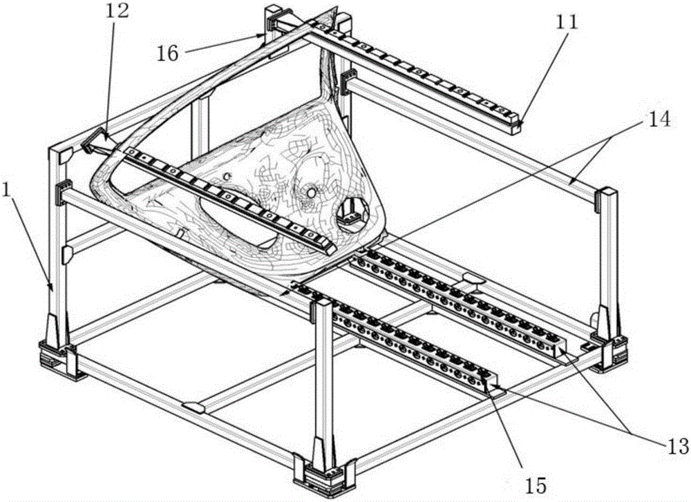
  • Automatic part placing material frame
  • Automatic part placing material frame
  • Automatic part placing material frame

Examples


Embodiment Construction

[0039] The following will clearly and completely describe the technical solutions in the embodiments of the present invention with reference to the accompanying drawings in the embodiments of the present invention. Obviously, the described embodiments are only some, not all, embodiments of the present invention. Based on the embodiments of the present invention, all other embodiments obtained by persons of ordinary skill in the art without creative efforts fall within the protection scope of the present invention.

[0040] It should be noted that, in the case of no conflict, the embodiments of the present invention and the features in the embodiments can be combined with each other.

[0041] The present invention will be further described below in conjunction with the accompanying drawings and specific embodiments, but not as a limitation of the present invention.

[0042] The invention includes a material frame for automatically placing parts.

[0043] Such as figure 1 As s...


PUM


Abstract

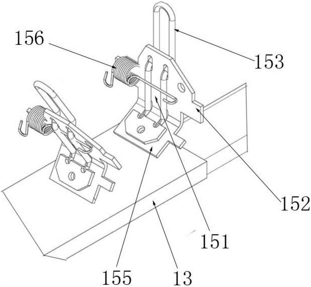
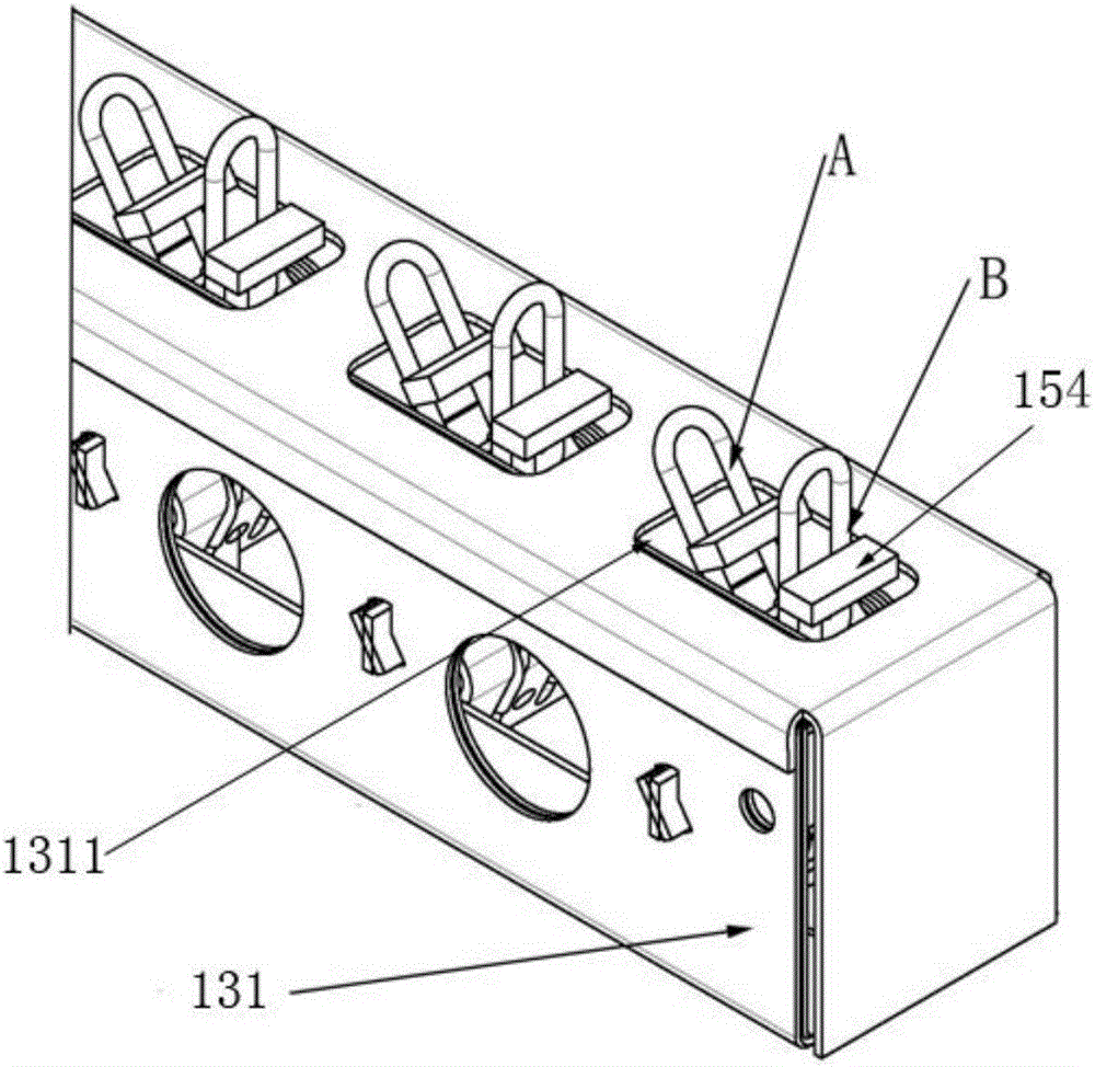
The invention provides an automatic part placing material frame. The material frame is applied to placing of parts. The material frame comprises a frame body, a first positioning rod arranged on the frame body, a second positioning rod arranged on the frame body, a pair of fixing rods and fixing devices; the second positioning rod and the first positioning rod are arranged at the preset interval; the first positioning rod and the second positioning rod are matched to support the tops of the parts; the fixing rods are arranged on a base of the frame body in parallel; each fixing rod is provided with plural fixing devices capable of turning over; and the fixing devices are used for fixedly supporting the bottoms of the parts, and the parts are limited on the frame body. The automatic part placing material frame has the beneficial effects that the parts placed on the frame body can be automatically fixed through the rotatable fixing devices arranged on the frame body, operation is easy, and the defect that in the prior art, the parts are placed in the material frame, a robot needs to be additionally arranged, and operation is inconvenient is overcome.

Description

technical field [0001] The invention relates to the field of assembly of automobile parts, in particular to a material frame for automatically placing parts. Background technique [0002] In the assembly process of automobile parts, especially when the door parts are placed in the predetermined material frame, the door parts are usually placed in the material frame by the robot, and in the process of placing the door parts by the robot, due to the door parts Due to its own irregular structure, when the door parts are placed in the material frame, the door parts will have a certain inclination angle, which will cause interference with the placement position of other door parts to be put into the material frame, which will cause other door parts to be unable to be placed. The feeding basket, in order to ensure that the next door part can be accurately put into the material frame, so in the prior art, when placing each door part, it is necessary to use the robot to place the pa...

Claims


Application Information

Patent Timeline
IPC IPC(8): B23P19/00
CPCB23P19/004
Inventor 朱益晨单齐勇陈铖童梁钱晖
Owner SHANGHAI FANUC ROBOTICS
Learn More