Heat insulation tank with outer skin plates
A technology of heat preservation tank and outer cover plate is applied in the field of special vehicles, which can solve the problems of easy damage of rivet joints, poor flatness of pressing plates, easy leakage, etc., and achieves the effects of good sealing, not easy to leak, and beautiful appearance.
- Summary
- Abstract
- Description
- Claims
- Application Information
AI Technical Summary
Problems solved by technology
Method used
Image
Examples
no. 1 example
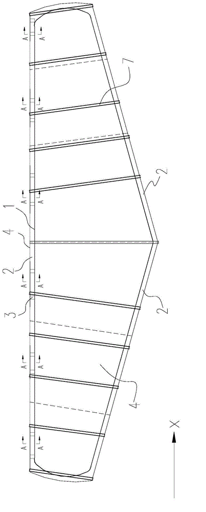
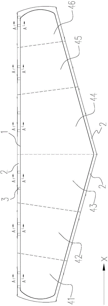
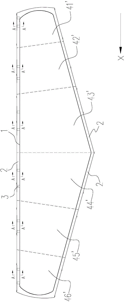
[0033] See figure 1 , which respectively show the front view of the insulation tank with the outer covering board of the present invention. In a preferred embodiment of the present invention, the thermal insulation tank with the outer covering board comprises: a tank body 1, an insulating layer 2, a plurality of supports 3, a plurality of outer covering boards 4, a plurality of connectors 5 (due to the thickness of the connectors 5 thinner, figure 1 not shown, see Figure 4 ) and tightening device.
[0034] Such as figure 1 As shown, the outer periphery of the tank body 1 is conical, and its bottom protrudes downward. The insulation layer 2 is coated on the outside of the tank body 1 . Although this embodiment takes a conical tank as an example, the present invention can also be applied to non-conical tanks such as cylinders.
[0035] A plurality of outer covering panels 4 are spliced together and covered on the outside of the insulation layer 2, thereby protecting the...
no. 2 example
[0046] See Figure 6 , which shows a schematic diagram of the connection structure among the connecting piece, the outer covering panel and the bracket according to the second embodiment of the present invention. with the above Figure 4 The difference of the illustrated embodiment is that the first insertion slot 51' and the second insertion slot 52' are located at the same level, and the longitudinal section of the connecting piece 5' is I-shaped. It can be understood that, in this embodiment, after the ends 411, 411' of the outer covering panels 41, 41' are fully inserted into the first insertion groove 51' and the second insertion groove 52', they are passed through two rivets 6 respectively. ' is fixedly connected with the connector 5'. Those skilled in the art understand that this embodiment can also be implemented, and details are not described here.
[0047] Furthermore, those skilled in the art understand that, in some other embodiments, the opening direction of th...
no. 3 example
[0049] See Figure 7 , which shows a structural schematic view of the vertical section of the insulation tank according to the third embodiment of the present invention. Among them, the insulation tank is also formed into a multi-segment outer covering plate covering area, such as Figure 7 shown, with the above image 3 The difference in the first embodiment is that each section of the outer covering plate is covered by an outer covering plate 47 along the circumference of the section, and after the outer covering plate 47 is wrapped around, its two ends 471, 472 are connected through the connecting piece 5. stitching.
[0050] Although in the above embodiments, the connection method between the connecting piece and the outer covering panel is mainly described by taking the connecting piece applied to the end of the outer covering panel as an example, the connecting piece can be applied to two outer covering panels other stitching parts. For example Figure 2a On the fir...
PUM
 Abstract
Description
Claims
Application Information
 - R&D
- Intellectual Property
- Life Sciences
- Materials
- Tech Scout
- Unparalleled Data Quality
- Higher Quality Content
- 60% Fewer Hallucinations
Browse by: Latest US Patents, China's latest patents, Technical Efficacy Thesaurus, Application Domain, Technology Topic, Popular Technical Reports.
© 2025 PatSnap. All rights reserved.Legal|Privacy policy|Modern Slavery Act Transparency Statement|Sitemap|About US| Contact US: help@patsnap.com


