Infrared magnetic field float yarn sensor for computer flat knitting machine

A flat knitting machine and infrared technology, applied in knitting, textiles and papermaking, etc., can solve the problems of increased production costs, increased labor costs, and reduced production efficiency, so as to improve production efficiency, protect needle beds, reduce labor costs and reduce production costs. cost effect

Active Publication Date: 2016-07-27
上海帝奇自动化设备有限公司
View PDF8 Cites 0 Cited by
  • Summary
  • Abstract
  • Description
  • Claims
  • Application Information

AI Technical Summary

Problems solved by technology

With the increase of social labor costs and increasingly fierce market competition, the floating yarn detection device in the prior art not only has the

Method used


Image

  • Infrared magnetic field float yarn sensor for computer flat knitting machine
  • Infrared magnetic field float yarn sensor for computer flat knitting machine
  • Infrared magnetic field float yarn sensor for computer flat knitting machine

Examples


Embodiment Construction

[0020] In order to make the purpose, technical solutions and advantages of the embodiments of the present invention more clear, the technical solutions in the embodiments of the present invention will be clearly and completely described below in conjunction with the drawings in the embodiments of the present invention. Apparently, the described embodiments are some, but not all, embodiments of the present invention. Based on the embodiments of the present invention, all other embodiments obtained by persons of ordinary skill in the art without creative efforts fall within the protection scope of the present invention.

[0021] The present invention will be further described in detail below in conjunction with the accompanying drawings.

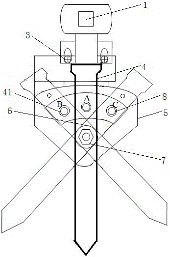
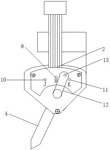
[0022] like figure 1 and figure 2 As shown, an infrared magnetic field floating yarn sensor for a computerized flat knitting machine provided by the present invention includes: an infrared probe 1, an infrared detection circuit board 2, a p...


PUM


Abstract

The invention relates to an infrared magnetic field float yarn sensor for a computer flat knitting machine. The infrared magnetic field float yarn sensor comprises an infrared probe, an infrared detection circuit board, positioning screws, a probe slice, a base station, a rotating hole, a positioning bolt, an LED lamp, a Hall switch H, a Hall switch J, a Hall switch K, a steel magnet and a rotating shaft, wherein the infrared probe is fixedly arranged by the positioning screws and is connected to the infrared detection circuit board, and the rotating hole penetrates through the base station; the middle end of the probe slice sleeves the front end of the rotating hole and then is fixed through the positioning bolt, and a round hole is also formed in the probe slice; the status of the LED lamp is displayed through the round hole, and the steel magnet is arranged at the front end of the rotating shaft; the rotating shaft is synchronously connected with the probe slice, and the Hall switch H, the Hall switch J and the Hall switch K are arranged in the infrared detection circuit board inside the base station according to preset positions. The float yarn sensor provided by the invention has the advantages of having high detecting precision, effectively avoiding a false alarm caused by slight jitter and mistaken collision of the probe slice, greatly improving production efficiency, and reducing production cost.

Description


Claims


Application Information

Patent Timeline
Owner 上海帝奇自动化设备有限公司
Why Eureka
Try Eureka