Indoor piling wall support structure and construction method therefor

A technology for supporting structures and pile walls, which is applied in the direction of foundation structure engineering, sheet pile walls, underwater structures, etc., can solve problems such as endangering the main building, and achieve the effects of preventing potential danger, eliminating common quality problems, and ensuring quality

Active Publication Date: 2016-07-27
JIANGXI THE SECOND CONSTR +1
View PDF6 Cites 3 Cited by
  • Summary
  • Abstract
  • Description
  • Claims
  • Application Information

AI Technical Summary

Problems solved by technology

[0003] However, when the support structure of the related technology occurs in an emergency such as an earthquake or during the construction of the support structure, the displacement or slight inclination of the support structure cannot be monitored and sensed in time, and there is a risk of harming the main building.

Method used


Image

  • Indoor piling wall support structure and construction method therefor
  • Indoor piling wall support structure and construction method therefor
  • Indoor piling wall support structure and construction method therefor

Examples


Embodiment Construction

[0032] The present invention is further described in conjunction with the following examples.

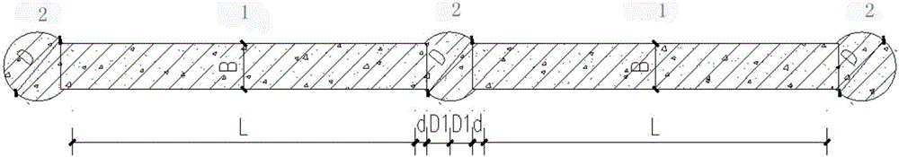
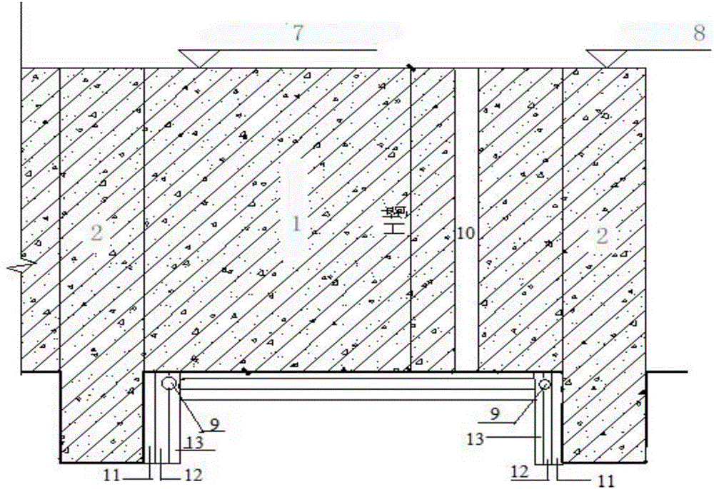
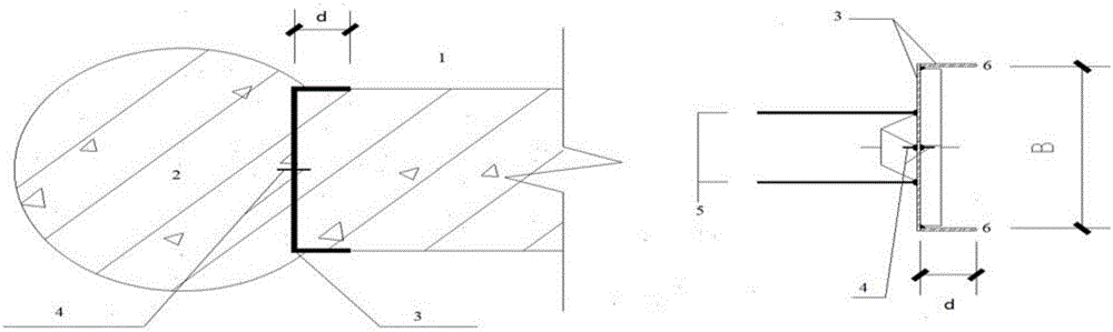
[0033] An indoor pile wall support structure provided by an embodiment of the present invention includes several ground connection walls 1 and several cast-in-situ piles 2 . The ground connection wall 1 is formed by a stirring method, a rotary spraying method or a compact grouting method. Cast-in-situ piles 2 are respectively arranged on both sides of each ground connection wall 1, and each ground connection wall 1 is connected to form a pile wall support structure by filling piles 2; Embedded part 3 overlaps and occludes; both ends of embedded part 3 extend horizontally along the outer surface of ground connection wall 1, and are folded to form embedded part flange 6 perpendicular to and parallel to the main body of embedded part 3; A water-stop component 4 is arranged on the part 3; the ground connection wall 1, the cast-in-place pile 2 and the water-stop component 4 form a water...


PUM


Abstract

The invention discloses an indoor piling wall support structure. The indoor piling wall support structure comprises underground diaphragm walls and cast-in-place piles, wherein the cast-in-place piles are arranged on two sides of each underground diaphragm wall respectively, and the underground diaphragm wall and each corresponding cast-in-place pile are in lap joint meshing through an embedded part embedded at edges of the underground diaphragm wall and the corresponding cast-in-place pile; two ends of each embedded part extend horizontally along the outer surface of the corresponding underground diaphragm wall and folded to form embedded part flanges which are perpendicular to a main body of the embedded part and are parallel to each other; a water stop component is arranged on each embedded part; the underground diaphragm walls, the cast-in-place piles and the water stop components constitute water stop piling walls; a cement mortar layer is arranged on the side, connected with the corresponding underground diaphragm wall, of each cast-in-place pile, and a pipe component pre-equipped with a wire and made of a waterproof insulating material is arranged in the cement mortar layer; a cement mortar layer, prefabricated thermal mortar soft boards and prefabricated waterproof soft boards are arranged sequentially on the outer wall surface of underground space formed between the bottoms of the underground diaphragm walls and the cast-in-place piles; a displacement sensor is arranged between the prefabricated thermal mortar soft boards at a junction of each underground diaphragm wall and each corresponding cast-in-place pile, and a wire of the displacement sensor extends to the wall top from the corresponding pipe component.

Description

technical field [0001] The invention relates to the field of construction, in particular to a pile-wall combined support structure and a construction method thereof. Background technique [0002] With the development of the economy, land resources become more and more tense. The depth of foundation pit excavation in construction projects is getting deeper and deeper, and the depth of many large buildings exceeds 15 meters, which requires higher requirements for foundation pit support structures. When excavating a foundation pit, the construction space of an underground structure, its side walls are likely to collapse into the pit, and a temporary reinforcement structure must be constructed to retain the soil to ensure the safety of the foundation pit and underground structures. The safety of existing structures around the foundation pit. [0003] However, when the support structure of the related technology occurs in an emergency such as an earthquake or during the constru...

Claims


Application Information

Patent Timeline
Patent Type & Authority Applications(China)
IPC IPC(8): E02D17/04E02D5/10E02D5/12E02D29/02
CPCE02D5/10E02D5/12E02D17/04E02D29/02
Inventor 肖锐
Owner JIANGXI THE SECOND CONSTR
Why Eureka
Try Eureka