Packer

A technology of packers and tubular parts, which is applied in sealing/isolation, wellbore/well parts, earthwork drilling and production, etc. It can solve the problems of difficult removal of packers and small radial expansion size of rubber tubes, etc.

Active Publication Date: 2016-07-27
SOUTHWEST PETROLEUM UNIV
View PDF6 Cites 12 Cited by
  • Summary
  • Abstract
  • Description
  • Claims
  • Application Information

AI Technical Summary

Problems solved by technology

[0004] However, the existing anti-outburst methods have the problem that the radial expansion

Method used


Image

  • Packer
  • Packer
  • Packer

Examples


Embodiment 1

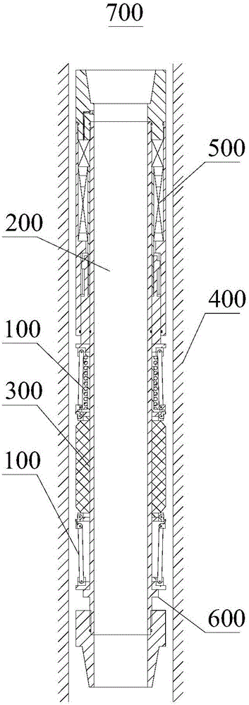
[0063] refer to figure 1 , the two anti-protrusion devices 100 are integrally sleeved on the tubular member 200 . The rubber cylinder 300 is sleeved on the tubular member 200, the rubber cylinder 300 is located between the two anti-protrusion devices 100, the driving device 500 is arranged at the upper end of the tubular member 200, and the limiting device 600 is arranged at the lower end of the tubular member 200, so that the structure is formed. A packer 700. The packer 700 is lowered into the wellbore 400 to separate and seal the wellbore 400 during setting.

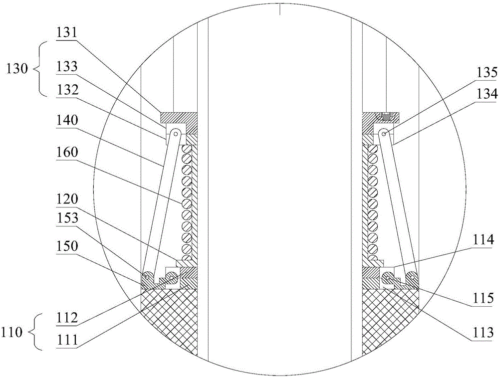
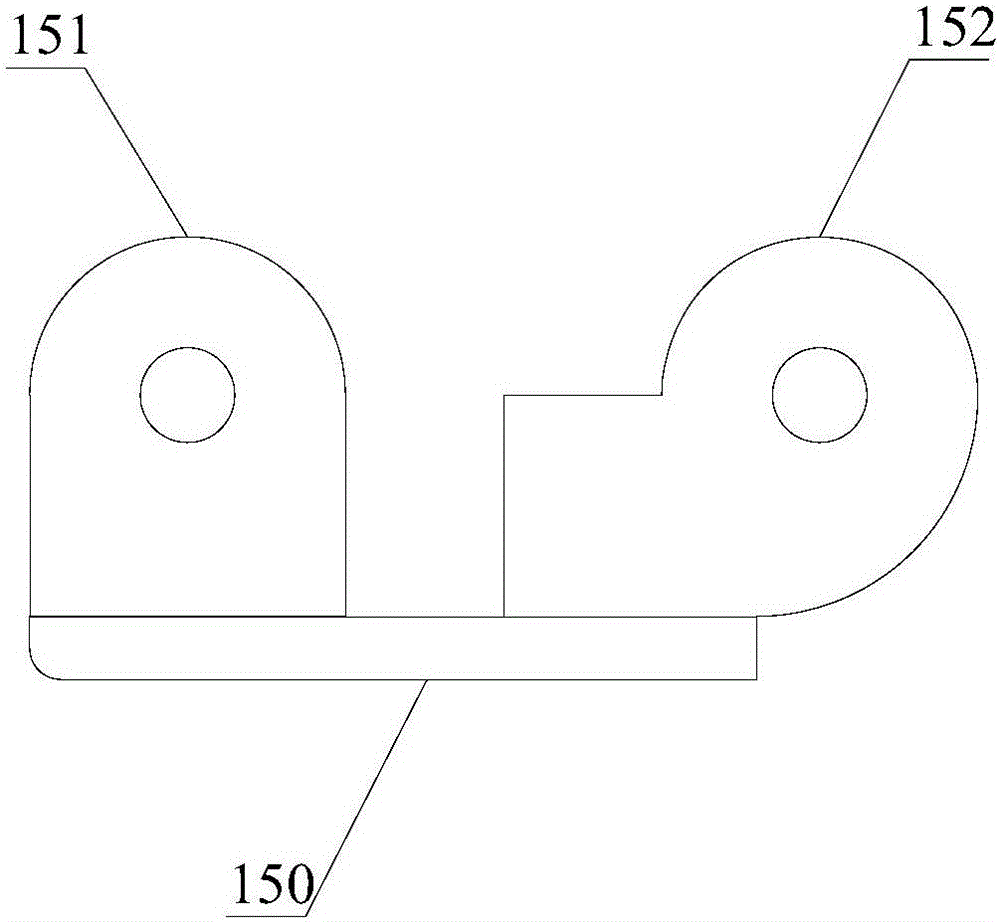
[0064] refer to figure 2 , the anti-slip device 100 includes a body and a wing plate 150 . The body includes an extrusion ring 110 , a limiting member 120 , a pressure bearing ring 130 and a connecting rod 140 .

[0065] The pressure-bearing ring 130 includes an annular pressure-bearing cover 131 and a pressure-bearing seat 132 . The pressure-bearing cover 131 and the pressure-bearing seat 132 are coaxially arran...

Embodiment 2

[0089] Compared with the first embodiment, the present embodiment is different in the driving device 500 and the limiting device 600, and the remaining parts are basically the same as those of the first embodiment.

[0090] refer to Figure 12 , the driving device 500 includes an outer sleeve 510 and a pressure sliding sleeve 540 . The inner surface of the upper joint 530 is fixed on the upper end of the tubular member 200 by screwing. The outer sleeve 510 is sleeved on the tubular member 200, and the outer sleeve 510 is threadedly connected with the outer surface of the upper joint 530 to realize fixing. An annular space with a closed lower end is formed between the inner surface of the outer sleeve 510 and the outer surface of the tubular member 200 . The pressure sliding sleeve 540 is slidably sleeved on the tubular member 200, and seals the open end of the annular space through the sealing rings arranged on the inner peripheral surface and the outer peripheral surface th...


PUM


Abstract

The invention discloses a packer. An annular space between a body and the inner surface of a shaft is sealed through a wing plate in an overturning mode; in this way, even if packer rubber needs to expand into a large size, the wing plate can cover and support the two ends of the packer rubber, and the packer is suitable for occasions where an annular space between a body and the inner surface of a shaft is large. Meanwhile, due to the fact that large-size radial expansion of the packer rubber can be achieved, it can be guaranteed that a large gap exists between the packer rubber and the inner surface of the shaft when the packer is lowered into the shaft, and then the packer can be placed in the shaft more easily.

Description

technical field [0001] The present invention relates to a packer for use in a wellbore. Background technique [0002] In the process of oil and gas production, it is necessary to plug the wellbore. A packer is used for plugging, the rubber cylinder is sleeved on the tubular member, and the rubber cylinder is placed under the tubular member at the position to be plugged downhole. The two ends of the rubber cylinder are pressed by the extrusion parts, and the rubber cylinder is radially expanded under pressure to seal and combine with the inner surface of the wellbore to complete the setting, so as to achieve the purpose of sealing and separation. [0003] After the rubber cylinder expands radially, the outer diameter of the rubber cylinder is larger than the outer diameter of the extrusion part, the extrusion part cannot effectively support the rubber cylinder, and part of the rubber will flow out between the extrusion part and the inner surface of the wellbore, causing the ...

Claims


Application Information

Patent Timeline
IPC IPC(8): E21B33/128
CPCE21B33/128E21B33/1285
Inventor 黎伟雷鸿翔袁圣桐罗献科陈检李果林
Owner SOUTHWEST PETROLEUM UNIV
Why Eureka
Try Eureka