Rail type gate micro valve device

An orbital and orbital technology, applied in valve devices, sliding valves, engine components, etc., can solve problems such as hindering gate impact, increasing process difficulty and actuation power consumption, avoiding necessity and enriching gate micro-valve structure design. Effect

Active Publication Date: 2016-07-27
ZHEJIANG DUNAN ARTIFICIAL ENVIRONMENT
View PDF8 Cites 2 Cited by
  • Summary
  • Abstract
  • Description
  • Claims
  • Application Information

AI Technical Summary

Problems solved by technology

However, in order to hinder the impact of the fluid on the gate in the direction of fluid movement, the gate of the gate microvalve generally adopts the form of a large mass block, such as in US Pat. It increases the difficulty of the process and the power consumption of the actuation, which limits the structural form and process flow of the gate microvalve to a certain extent.

Method used


Image

  • Rail type gate micro valve device
  • Rail type gate micro valve device
  • Rail type gate micro valve device

Examples


Embodiment 1

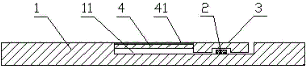
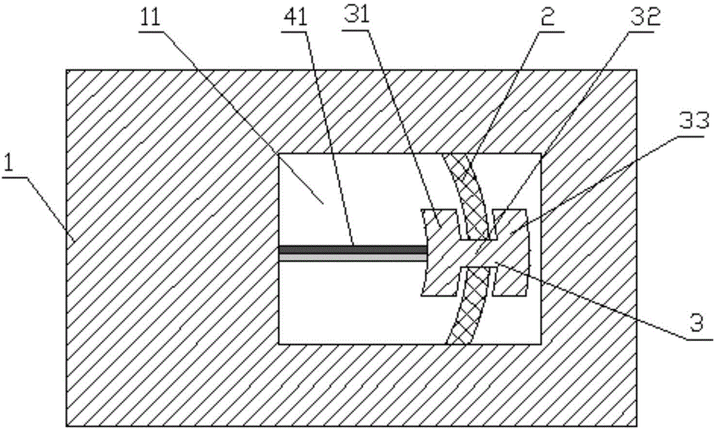
[0021] Embodiment 1 of the present invention is described below. The orbital gate microvalve of the present invention is formed by bonding double-layer silicon wafers, including a first silicon wafer on the upper layer and a second silicon wafer on the lower layer. Such as figure 1 with figure 2 As shown, a groove 11 is provided at the bottom of the first layer of silicon wafer 1 , and a microvalve track 2 , a moving member 3 and an actuating beam 4 are arranged in the bottom groove of the first layer of silicon wafer 1 . Among them, such as image 3 As shown, the microvalve track 2 is a convex track protruding from the bottom surface of the bottom groove. The microvalve track 2 can be formed of a material with sufficiently smooth surface, which can reduce the movement resistance to the moving member during the contact process. In order to further reduce the movement resistance, the microvalve track extends in an arc shape. The moving member 3 and the actuating beam 4 form...

Embodiment 2

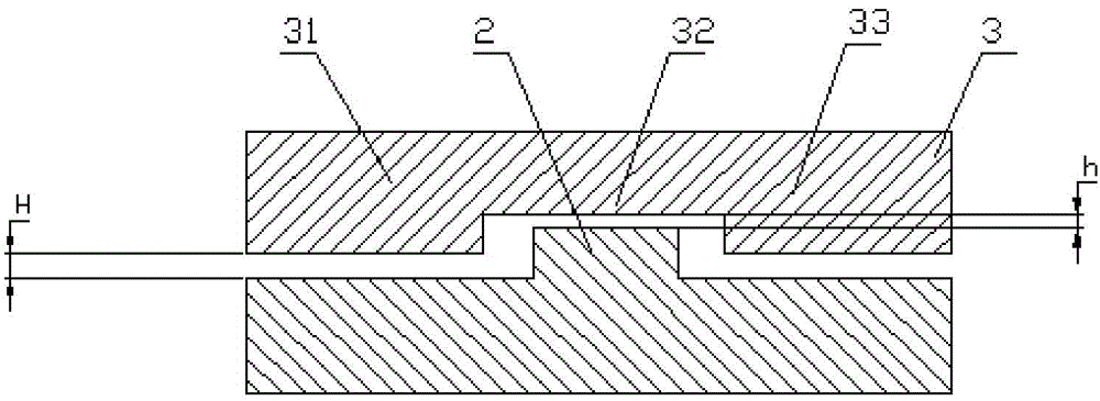
[0029] In this implementation example, the cooperation structure between the microvalve track and the moving member is as follows: Figure 4 As shown, the convex track is provided with a track groove away from the side of the actuating beam. The moving member is composed of a gate, a limiting beam and a compensating beam. The beam connected to the actuating beam is a gate, and the vertical beam connected to the end of the gate is Compensation beam, and one end of the limit beam is connected to the compensation beam, and the other end extends into the track groove. The distance between the limiting beam and the upper and lower tracks inside the track groove is h, and the distance between the gate and the upper surface outside the track groove is H. This structural design is mainly to limit the vertical direction under the impact of fluid. The displacement is between the upper and lower orbits.

Embodiment 3

[0031] This implementation example is Figure 5 As shown, the basic structure is similar to that of Example 2, except that the compensation beam and the limiting beam are on the side of the microvalve track close to the actuating beam. Between the upper track and the lower track on one side.


PUM


Abstract

The invention discloses a rail type gate micro valve device. The rail type gate micro valve device is formed by an upper silicon wafer layer and a lower silicon wafer layer in a bonding mode. The bottom of the first silicon wafer layer is provided with a groove. The second silicon wafer layer is provided with a fluid inlet, a fluid outlet and a control port, and the fluid inlet, the fluid outlet and the control port penetrate through the second silicon wafer layer up and down. A micro valve rail, a moving part and an actuating beam are arranged in the groove of the bottom of the first silicon wafer layer. The moving part is arranged on the micro valve rail. One end of the actuating beam is connected to the sidewall of the bottom groove, and the other end of the actuating beam is connected to the moving part. The actuating beam is connected with a bimetal thermal actuator. A gate is arranged on the moving part. The actuating beam is used for driving the moving part to move along the micro valve rail so as to control the gate to open or close the fluid inlet and the fluid outlet. According to the rail type gate micro valve device, a high-mass gate is avoided, and the possibility of more plentiful gate micro valve structure design is provided.

Description

technical field [0001] The invention relates to silicon valves in the field of micro-electromechanical systems. Background technique [0002] There are many types of commonly used micro valves, but the processing objects are mostly microfluids such as cells and DNA, the flow rate is small, and the pressure is relatively low. There are relatively few applications in the medical and biological fields, mainly because the traditional diaphragm micro valve structure is difficult to adapt to the application environment of high pressure and large flow in industrial production. [0003] Because the gate movement direction is perpendicular to the fluid flow direction in the valve, the gate microvalve is more suitable for the application requirements of high-pressure and large-flow beams in structure, and has gradually become a research hotspot in the industrial application of micro-valve. However, in order to hinder the impact of the fluid on the gate in the direction of fluid movem...

Claims


Application Information

Patent Timeline
Patent Type & Authority Applications(China)
IPC IPC(8): F16K3/02F16K3/30
Inventor 邓宁李勇俊张胜昌段飞
Owner ZHEJIANG DUNAN ARTIFICIAL ENVIRONMENT
Why Eureka
Try Eureka