optical mechanism

An optical mechanism and bushing technology, applied in optics, optical components, installation, etc., can solve the problems of mutual influence of strokes and strokes, and achieve the effect of stable operation, maintaining stability, and excellent coaxial accuracy.

Active Publication Date: 2018-07-13
ASIA OPTICAL CO INC +1
View PDF3 Cites 0 Cited by
  • Summary
  • Abstract
  • Description
  • Claims
  • Application Information

AI Technical Summary

Problems solved by technology

[0005] The technical problem to be solved by the present invention is to provide an optical mechanism that solves the problem when the group frame has a longer bushing in view of the above-mentioned defects in the prior art that the strokes affect each other when the group frame has a longer bushing. The problem of the mutual influence of the itinerary caused by the

Method used


Image

  • optical mechanism
  • optical mechanism
  • optical mechanism

Examples


Embodiment Construction

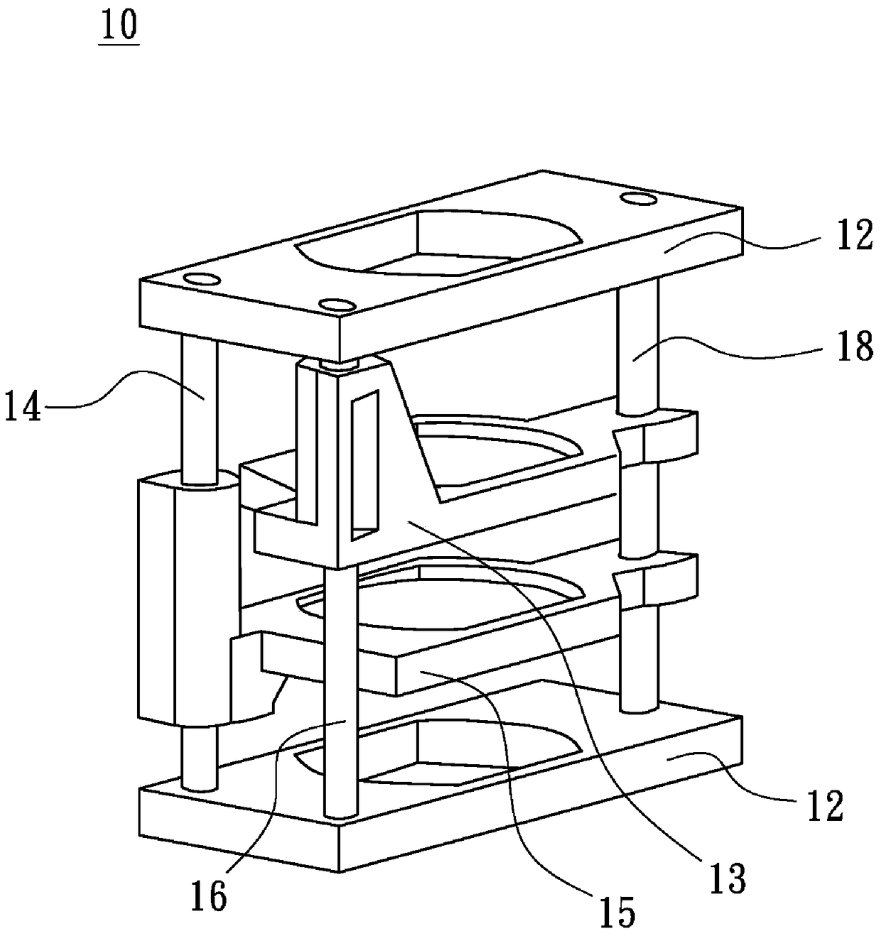
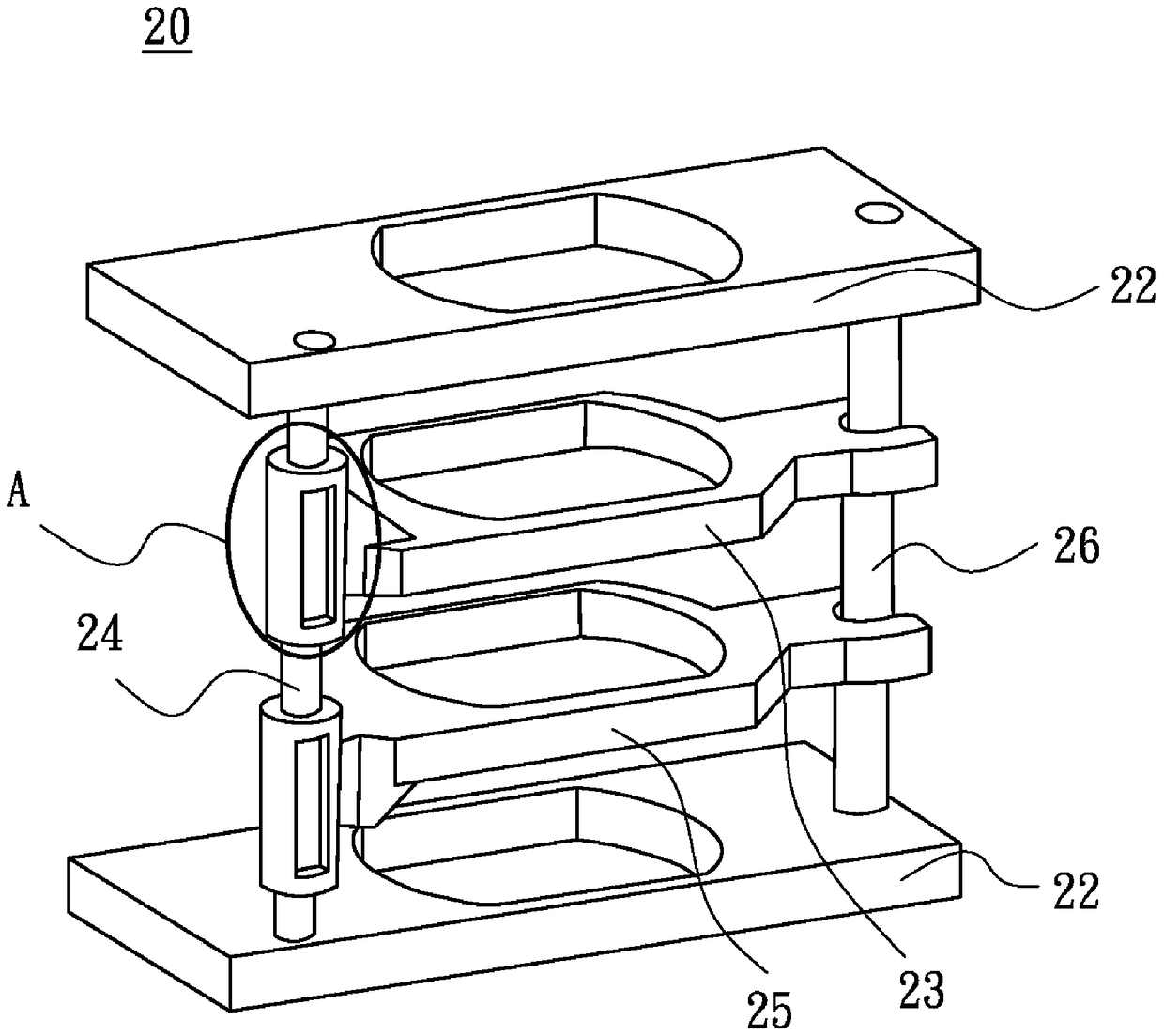
[0025] see Figure 4 , 5 , which represents the optical mechanism of the present invention. The optical mechanism 100 of the present invention includes a base 120 , a main shaft 140 , a secondary shaft 160 , a first group frame 130 and a second group frame 150 . The base 120 is divided into an upper base 122 and a lower base 124. The upper base 122 and the lower base 124 are plate-shaped and arranged parallel to each other. The main shaft 140 and the auxiliary shaft 160 are arranged between the upper base 122 and the lower base 124. , and the primary axis 140 is parallel to the secondary axis 160 .

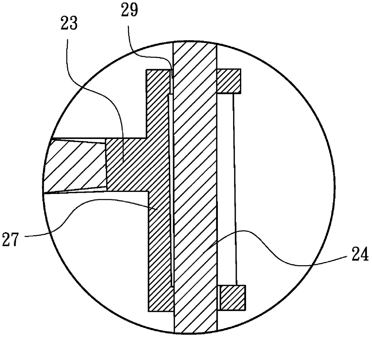
[0026] The first group frame 130 can carry a first lens group (not shown) and has a first bushing 131 and a third bushing 133, the first bushing 131 and the third bushing 133 are respectively arranged on the first group frame 130. On opposite sides, the first bushing 131 is movably disposed on the main shaft 140 , and the third bushing 133 is movably disposed on the auxiliary s...


PUM


Abstract

An optical mechanism includes a base, a main shaft, a first group frame and a second group frame. The main shaft is arranged on the base, the first group frame carries the first lens group and has a first bushing, and the first bushing is movably combined with the main shaft, and the second group frame carries the second lens group and has a second A bushing, the second bushing is movably combined with the main shaft, wherein the first bushing and the second bushing are overlapped on the main shaft.

Description

technical field [0001] The present invention relates to an optical mechanism, in particular to an optical mechanism in which a lens-carrying group frame has a long bushing and the bushings overlap each other. Background technique [0002] In the known optical lens, each group frame is guided by the main shaft to move along the main shaft to produce zooming and focusing effects. [0003] see figure 1 , which represents the combination of each group frame and the main axis in the known optical mechanism. The optical mechanism 10 has a base 12 , a first main shaft 14 , a second main shaft 16 , a sub shaft 18 , a first group frame 13 and a second group frame 15 . The first main shaft 14, the second main shaft 16 and the auxiliary shaft 18 are arranged on the base 12, the first group frame 13 carries the first lens group (not shown), and the second group frame 15 carries the second lens group (not shown). ), the first group frame 13 can be moved by being guided by the first ma...

Claims


Application Information

Patent Timeline
Patent Type & Authority Patents(China)
IPC IPC(8): G02B7/10
CPCG02B7/10
Inventor 施旭彦
Owner ASIA OPTICAL CO INC
Why Eureka
Try Eureka