Method for realizing perfectly matched layer through auxiliary differential equation in plasma

A completely matched layer and plasma technology, applied in the field of computational electromagnetics, can solve the problems of poor low-frequency falling wave absorption and slow calculation speed.

Active Publication Date: 2016-07-27
XIAN UNIV OF TECH
View PDF4 Cites 6 Cited by
  • Summary
  • Abstract
  • Description
  • Claims
  • Application Information

AI Technical Summary

Problems solved by technology
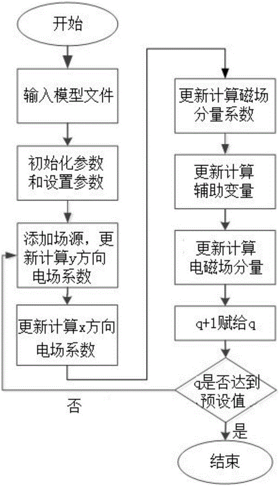
[0004] The purpose of the present invention is to provide a method for realizing the complete matching layer of the auxiliary differential equation in the plasma, which solves the problems of slow calculation speed and poor absorption of low frequency and litter waves when solving the electromagnetic problems in the magnetized plasma. The problem

Method used


Image

  • Method for realizing perfectly matched layer through auxiliary differential equation in plasma
  • Method for realizing perfectly matched layer through auxiliary differential equation in plasma
  • Method for realizing perfectly matched layer through auxiliary differential equation in plasma

Examples


Embodiment

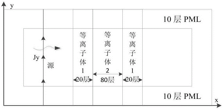
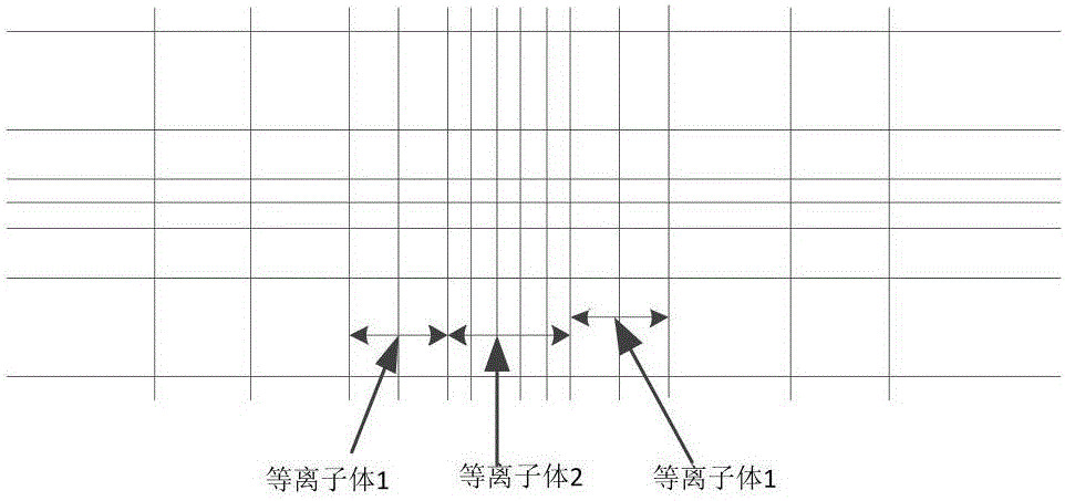
[0192] Select a non-uniform plasma plate with a thickness of 6mm, and calculate its reflection and transmission coefficients for electromagnetic waves. Simulation model such as figure 2 shown. The calculation area is 180×36 grids, and the grids from the 31st to the 150th along the x direction are non-uniform plasmas, among which plasma 1 occupies the 31st to 50th grids and the 131st to 150th grids lattice, the thickness is 1.5 mm, and its plasma parameter is ω p =1.80327×10 11 rad / s, υ=2×10 10 rad / s, plasma 2 occupies the 51st to 130th grid, the thickness is 3 mm, and its plasma parameter is ω p =5.6985×10 10 rad / s, υ=2×10 10 rad / s. Use a gradient non-uniform mesh to mesh the solution area, and the mesh near the non-uniform plasma is as follows image 3 As shown, the grid size of plasma 2 along the x direction is 37.5 μm, the grid size of plasma 1 is 75 μm, the grid size of other calculation areas is 150 μm, and the minimum grid size is 37.5 μm×37.5 μm. The source ad...


PUM


Abstract

The invention discloses a method for realizing a perfectly matched layer through an auxiliary differential equation in plasma. The method comprises the following specific steps: 1, inputting a model file; 2, performing initialization and setting a parameter of the model file in the step 1; 3, calculating an electric field component coefficient E<y><q> by using the parameter in the step 2; 4, calculating an electric field component coefficient E<x><q> by using the parameter in the step 2; 5, calculating a magnetic field component coefficient H<z><q> by using the electric field component coefficients obtained in the step 3 and the step 4; 6, calculating intermediate variable coefficients psi<x><q> and psi<y><q> by using the electric field component coefficients in the step 3 and the step 4; 7, updating and calculating an auxiliary variable of an electromagnetic field component coefficient in a whole computational domain; 8, updating and calculating an electromagnetic field component of an observation point; and 9, assigning q+1 to q, judging whether q is up to a preset value or not, returning the step 3 if q is not up to the preset value, and ending if q is up to the preset value. The method has the advantages of low calculation speed, low memory consumption, and very good absorption effects on low-frequency and evanescent waves.

Description

technical field [0001] The invention belongs to the technical field of computational electromagnetics, and in particular relates to a method for realizing a complete matching layer using auxiliary differential equations in plasma. Background technique [0002] It is well known that the time step of the Finite-difference time-domain (FDTD) method is limited by the Cauchy stability condition, which limits the application of the FDTD method in fine structure models. In order to eliminate the limitation of the Cauchy stability condition, unconditional stable finite difference time domain methods have been proposed, such as: Alternating-Direction-Implicit (Alternating-Direction-Implicit, ADI's finite difference time domain (ADI-FDTD)) method and based on weighted Laguerre polynomials Finite-difference time-domain (WLP-FDTD) method. Among these methods, the WLP-FDTD method can not only eliminate the limitation of the Cauchy stability condition, but also solve the problem that the...

Claims


Application Information

Patent Timeline
Patent Type & Authority Applications(China)
IPC IPC(8): G06F17/13
CPCG06F17/13
Inventor 席晓莉方云张金生刘江凡
Owner XIAN UNIV OF TECH
Why Eureka
Try Eureka