CVBS signal compression/decompression method, CVBS signal transmitting/receiving device and CVBS signal transmitting/receiving system

A signal compression and decompression technology, applied in the components of TV systems, image communication, selective content distribution, etc., can solve the problem that the amount of video transmission data cannot meet the actual requirements, and achieve improved bandwidth utilization and bandwidth reduction. , the effect of increasing the amount of data transmitted

Active Publication Date: 2016-07-27
CAPITAL MICROELECTRONICS
View PDF5 Cites 1 Cited by
  • Summary
  • Abstract
  • Description
  • Claims
  • Application Information

AI Technical Summary

Problems solved by technology

[0004] Embodiments of the present invention provide a CVBS signal compression / decompression method, transmitter / receiver and system to solve the technical problem that the amount of data in video transmission in the prior art is limited by the bandwidth and cannot meet the actual requirements. Under the bandwidth, increase the amount of video signal transmitted by the system and improve bandwidth utilization

Method used


Image

  • CVBS signal compression/decompression method, CVBS signal transmitting/receiving device and CVBS signal transmitting/receiving system
  • CVBS signal compression/decompression method, CVBS signal transmitting/receiving device and CVBS signal transmitting/receiving system
  • CVBS signal compression/decompression method, CVBS signal transmitting/receiving device and CVBS signal transmitting/receiving system

Examples


Embodiment Construction

[0045] In order to enable those skilled in the art to better understand the solutions of the present invention, the following will clearly and completely describe the technical solutions in the embodiments of the present invention in conjunction with the drawings in the embodiments of the present invention. Obviously, the described embodiments are only It is an embodiment of a part of the present invention, but not all embodiments. Based on the embodiments of the present invention, all other embodiments obtained by persons of ordinary skill in the art without creative efforts shall fall within the protection scope of the present invention.

[0046] The following is a detailed and public description of the technical solutions of the embodiments of the present invention.

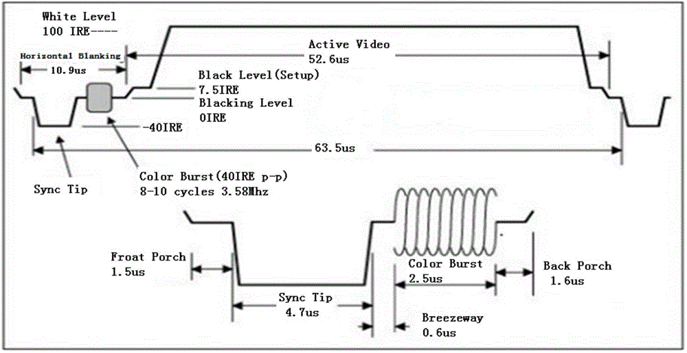
[0047] refer to Figure 1a As shown, it is a waveform diagram of a CVBS (CompositeVideoBroadcastSignal or CompositeVideoBlankingandSync, composite video broadcast signal or composite video blanking and synchro...


PUM


Abstract

An embodiment of the invention discloses a CVBS signal compression / decompression method, a CVBS signal transmitting / receiving device and a CVBS signal transmitting / receiving system that are applied to the technical field of video signal processing. A large quantity of signals can be transmitted with a certain bandwidth, and a bandwidth utilization rate can be improved. The CVBS signal compression method mainly comprises the following steps: a first step of detecting quantified CVBS signals, a second step of determining leading edge data of a current synchronization pulse, and a third step of compressing data contained in the CVBS signals in order. The third step comprises the following steps: preset code words used for indicating the synchronization pulse are written into a first FIFO storage device, and a channel quantization value and a color load wave quantization value are directly written into the first FIFO storage device; compression values, determined via a compression table, corresponding to all quantization values between the color load wave and a next synchronization pulse are written into the first FIFO storage device; the compression table is used for storing mapping relations between the quantization values and compression values.

Description

technical field [0001] The invention relates to the technical field of video signal processing, in particular to a CVBS signal compression / decompression method, transmitter / receiver and system. Background technique [0002] CVBS (CompositeVideoBroadcastSignal or CompositeVideoBlankingandSync, Composite Video Broadcast Signal or Composite Video Blanking and Synchronization) is a widely used image data transmission standard. It transmits data in an analog waveform. Composite video contains color difference (hue and saturation) and luminance (brightness) information and synchronizes them in pedestal pulses and transmits them on the same signal. [0003] Most of the current TV signal transmission uses the CVBS transmission method, and the increase in demand for TV signals puts forward new requirements for the transmission technology of video signals. However, the bandwidth of the current video signal transmission is limited, which limits the data volume of the video signal tra...

Claims


Application Information

Patent Timeline
Patent Type & Authority Applications(China)
IPC IPC(8): H04N21/2383H04N21/426H04N5/38H04N5/44
Inventor 陈东魁邵屹峰王岳
Owner CAPITAL MICROELECTRONICS
Why Eureka
Try Eureka