A new type of battery case injection mold

A technology for injection molds and batteries, which is applied in the field of injection molds for new battery casings. It can solve the problems of increasing the difficulty of injection molding workers, uneven thickness of finished plastic, and consuming a lot of time and energy, so as to achieve efficient and fast injection molding process and reduce manpower and material resources. input, the effect of reducing work difficulty

Active Publication Date: 2018-09-28
SONGUO MOTORS CO LTD
View PDF4 Cites 0 Cited by
  • Summary
  • Abstract
  • Description
  • Claims
  • Application Information

AI Technical Summary

Problems solved by technology

[0002] When plastic products are injection molded, the method of mold pressing is often used. At a certain temperature, the completely molten plastic material is stirred by a screw, injected into the mold cavity with high pressure, and after cooling and solidifying, the molded product is obtained. The previous method The injection molding method of the mold usually has an injection port at the bottom of the mold. This injection molding method is likely to cause a low yield rate, and the plastic thickness of the finished product is uneven, which affects the later processing and use, and the plastic injection port has a protruding part that needs to be processed. , not only takes a lot of time and energy, but also wastes plastic raw materials, which is not conducive to efficient injection molding production, thus increasing the work difficulty of injection molding staff

Method used


Image

  • A new type of battery case injection mold
  • A new type of battery case injection mold
  • A new type of battery case injection mold

Examples


Embodiment Construction

[0016] The technical solutions in the embodiments of the present invention will be clearly and completely described below in conjunction with the accompanying drawings in the embodiments of the present invention. Obviously, the described embodiments are only some of the embodiments of the present invention, not all of them. Based on the embodiments of the present invention, all other embodiments obtained by persons of ordinary skill in the art without making creative efforts belong to the protection scope of the present invention.

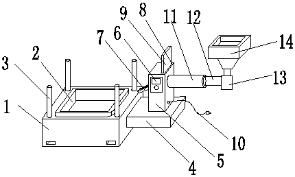
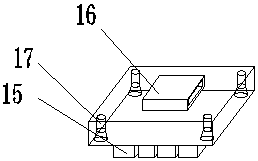
[0017] see figure 1 , the present invention provides a technical solution: a new battery casing injection mold, including a mold body 1, a die 2, a material cutting control box 5 and a punch 15, the die body 1 is provided with a die 2, the mold body 1 front The sides are provided with card slots, which can be easily fixed and improve stability. The four corners of the die 2 are provided with limit columns 3, the right side of the mold body 1 is pro...


PUM


Abstract

The invention discloses a novel injection mold for storage battery cases. The injection mold comprises a main mold body, a concave mold, a cutting control box and a convex mold, wherein the concave mold is arranged on the main mold body, limiting stand columns are arranged on side surfaces of four corners of the concave mold, a base plate is arranged on the right side of the main mold body, the cutting control box is arranged on the base plate, an operation panel is arranged on the front side of the cutting control box, a discharging nozzle is arranged on the left side of the cutting control box, a telescopic port is formed in the upper side of the cutting control box, a counterweight plate is arranged inside the telescopic port, the right side of the cutting control box is connected with a power line, and a melt quantitative molding pipe is arranged on the right side of the cutting control box. With the adoption of the novel injection mold for the storage battery cases, accurate control can be performed according to the specific material consumption, the manpower and material resource input can be greatly reduced, mold combination can be realized more accurately, an efficient and quick injection molding process is realized, the working difficulty of injection molding workers is greatly reduced, and the injection mold can be conveniently popularized and used in the market in a large scale.

Description

technical field [0001] The present invention relates to the technical field of injection molding tools, in particular to a new type of injection mold for battery shells. Background technique [0002] When plastic products are injection molded, the method of mold pressing is often used. At a certain temperature, the completely molten plastic material is stirred by a screw, injected into the mold cavity with high pressure, and after cooling and solidifying, the molded product is obtained. The previous method The injection molding method of the mold usually has an injection port at the bottom of the mold. This injection molding method is likely to cause a low yield rate, and the plastic thickness of the finished product is uneven, which affects the later processing and use, and the plastic injection port has a protruding part that needs to be processed. , not only takes a lot of time and energy, but also wastes plastic raw materials, which is not conducive to efficient injectio...

Claims


Application Information

Patent Timeline
Patent Type & Authority Patents(China)
IPC IPC(8): B29C45/26B29C45/18
CPCB29C45/1808B29C45/2602
Inventor 谢丹
Owner SONGUO MOTORS CO LTD
Why Eureka
Try Eureka