Efficient energy-saving high-output continuous delivery pump

A high-efficiency, energy-saving, and high-efficiency technology, applied in the field of delivery pumps, can solve problems such as low work efficiency, small delivery volume, and large energy consumption, and achieve high work efficiency, fast delivery speed, and improved delivery efficiency.

Inactive Publication Date: 2016-08-03
TIANJIN SHIDA ELECTRIC POWER EQUIP
View PDF6 Cites 1 Cited by
  • Summary
  • Abstract
  • Description
  • Claims
  • Application Information

AI Technical Summary

Problems solved by technology

The pneumatic conveying device has a simple structure and is easy to operate. It can be used for horizontal, vertical or inclined conveying. During the conveying process, it can also perform physical operations such as heating, cooling, drying and air classification of materials or certain chemical operations. The existing traditional pneumatic conveying is an intermittent conveying method with low working efficiency, large energy consumption and small conveying volume

Method used


Image

  • Efficient energy-saving high-output continuous delivery pump
  • Efficient energy-saving high-output continuous delivery pump

Examples


Embodiment Construction

[0013] The following will clearly and completely describe the technical solutions in the embodiments of the present invention with reference to the accompanying drawings in the embodiments of the present invention. Obviously, the described embodiments are only some, not all, embodiments of the present invention.

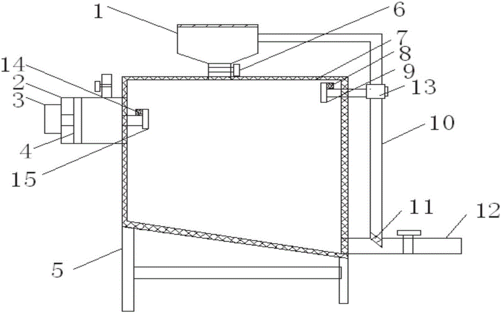
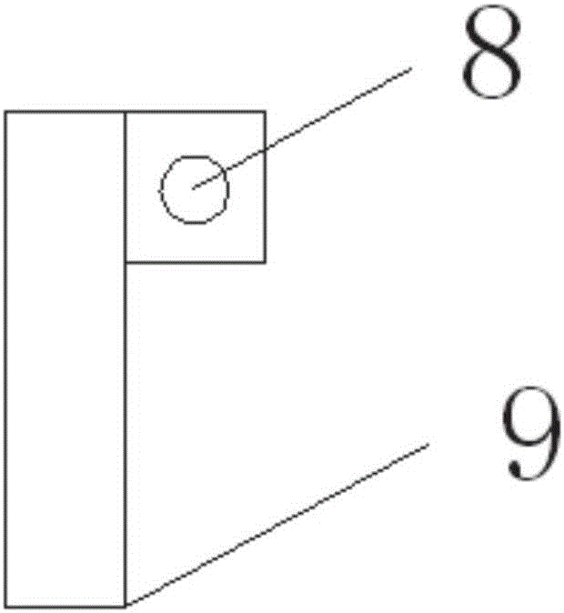
[0014] refer to Figure 1-2 , a high-efficiency, energy-saving, and high-efficiency continuous delivery pump, including a pressurized bin 2, a delivery bin 7, and a bin 1. The top of the bin 1 is provided with an upper cover, and one side of the upper cover is hinged to the bin 1. The bin 1 The bottom of the first feeding pipe is provided with a first electric control valve 6, the bottom of the first feeding pipe is connected with a delivery chamber 7, and one side of the delivery chamber 7 is provided with a pressurized chamber 2. A second air intake pipe is provided on the top of the pressurized chamber 2, and a second electric control valve is provided on the seco...


PUM


Abstract

The invention discloses a high-efficiency, energy-saving and high-efficiency continuous conveying pump, which comprises a pressurized bin, a conveying bin and a feeding bin. The bottom of the warehouse is provided with a first feeding pipe, and a first electric control valve is provided on the first feeding pipe. Pressure chamber, the top of the pressurization chamber is provided with a second air intake pipe, and the second air intake pipe is provided with a second electric control valve, the other side of the pressurization chamber is provided with a telescopic motor, and the output shaft of the telescopic motor A moving plate is connected, and the moving plate is slidably connected to the inner wall of the pressurized chamber. The side of the pressurized chamber close to the delivery chamber is provided with a second air delivery pipe, and the other end of the second air delivery pipe is connected with a second stopper. plate, and a second fixing rod is provided on one side of the second baffle plate. The invention has the advantages of simple structure, economy and practicality, fast conveying speed, high working efficiency and energy-saving function.

Description

technical field [0001] The invention relates to the technical field of conveying pumps, in particular to a continuous conveying pump with high efficiency, energy saving and large output. Background technique [0002] Pneumatic conveying, also known as airflow conveying, uses the energy of airflow to convey granular materials along the direction of airflow in a closed pipeline, which is a specific application of fluidization technology. The pneumatic conveying device has a simple structure and is easy to operate. It can be used for horizontal, vertical or inclined conveying. During the conveying process, it can also perform physical operations such as heating, cooling, drying and air classification of materials or certain chemical operations. The existing traditional pneumatic conveying is an intermittent conveying method with low working efficiency, large energy consumption and small conveying volume. Contents of the invention [0003] The object of the present invention ...

Claims


Application Information

Patent Timeline
Patent Type & Authority Applications(China)
IPC IPC(8): B65G53/16B65G53/36B65G53/46B65G53/52B65G53/58
CPCB65G53/16B65G53/36B65G53/46B65G53/52B65G53/58B65G2201/042
Inventor 黄申王宝国孙计亮郭富强刘海波付仲楠马辉
Owner TIANJIN SHIDA ELECTRIC POWER EQUIP
Why Eureka
Try Eureka