Nozzle

A nozzle and body technology, applied in the field of nozzles, can solve problems such as air pollution, increased cost of electricity, increased purchase costs of electroplating liquid and other industrial chemical liquids, and the cost of waste liquid treatment, etc., to achieve high liquid ejection volume Effect

Active Publication Date: 2016-08-03
UNITED BENEFIT
View PDF3 Cites 3 Cited by
  • Summary
  • Abstract
  • Description
  • Claims
  • Application Information

AI Technical Summary

Problems solved by technology

Therefore, operators who use dual-fluid nozzles need to install an exhaust device near the electroplating tank or other types of tanks to reduce air pollution inside the plant, but this will definitely increase the cost of purchasing and installing the exhaust device, and the cost of the exhaust device The cost of electricity consumed, etc. In addition, the air extraction device also occupies space, and the poisonous gas is pumped out of the factory building, causing the air outside the factory building to be polluted, which in turn affects the health of neighbors, etc.
[0008] 3. The high-pressure gas will increase the amount of bubbles in the electroplating solution and other liquids, which will affect the uniformity of the electroplating solution and other liquids sprayed on the target objects such as circuit boards, and seriously affect the processing quality of electroplating and other aspects.
[0009] 4. Oxygen and other components in the high-pressure gas will react with some chemical components in the electroplating liquid and other industrial chemical liquids, resulting in accelerated deterioration of the electroplating liquid and other industrial chemical liquids, reducing the durability of the electroplating liquid and other industrial chemical liquids. The service life, the frequency of replacement of electroplating liquid and other industrial chemical liquid by the industry is increased, and the purchase cost of electroplating liquid and other industrial chemical liquid and the cost of waste liquid treatment are increased

Method used


Image

  • Nozzle
  • Nozzle
  • Nozzle

Examples


Embodiment Construction

[0058] The embodiments of the present invention will be described in more detail below with reference to the drawings and reference numerals, so that those skilled in the art can implement them after studying this specification.

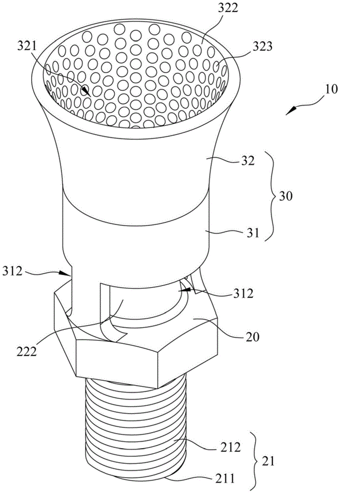
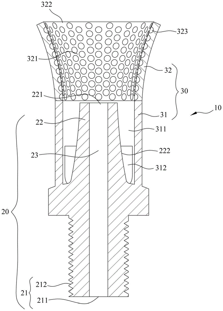
[0059] Please refer to figure 1 , figure 2 , the present invention provides a nozzle 10 including a body 20 and a cover 30 .

[0060] The body 20 includes a water inlet 21 and a water outlet 22 . The water inlet 21 forms a water inlet 211 and is installed on a liquid source. Preferably, the water inlet 21 includes an outer peripheral surface 212, and the outer peripheral surface 212 of the water inlet 21 is screwed to the liquid source, so that the water inlet 211 communicates with the inner space of the liquid source. The water outlet 22 forms a water outlet 221 and has an outer peripheral surface 222 . The main body 20 encloses a waterway 23 inside, and the waterway 23 runs through the water inlet 21 and the water outlet 22 and communicates be...


PUM


Abstract

The invention relates to a nozzle, which comprises a nozzle body and a cover body. The nozzle body comprises an outlet end and an enclosing water channel. The cover body comprises a connecting piece and a flow-increasing member. The connecting piece is arranged between the flow-increasing member and the nozzle body, the connecting piece encloses a hollow part and forms a side water inlet hole, and the side water inlet hole is communicated with the hollow part. The flow-increasing member forms a through groove and a water outlet opening. The through groove is communicated with a space between the water outlet opening and the hollow part, at least one wall surface of the water channel, an outer peripheral surface of the water outlet end, the hollow part, and the through groove is an uneven surface. liquid flow generates turbulent flow when passes through the uneven surface, so that a spraying angle of liquid is greater than 30 DEG. When the nozzle provided by the invention is taken as the single fluid nozzle, the nozzle has advantage of the single-fluid nozzle and a two-fluid nozzle, and can improve the disadvantages of the current single-fluid nozzle and the two-fluid nozzle. In addition, the external liquid can be introduced through the side water inlet hole, so that efficacy of high liquid spraying amount is achieved.

Description

technical field [0001] The present invention relates to a nozzle. Background technique [0002] A nozzle is a tool that is often used to atomize and eject liquids. Commonly used nozzles can be divided into single-fluid nozzles and dual-fluid nozzles according to the principle of liquid atomization. The single-fluid nozzle uses a pump to pressurize the liquid, so that the liquid is sprayed out through the water nozzle, so it is also called a liquid pressurized nozzle. The two-fluid nozzle introduces high-pressure gas and impacts the liquid with its power, thereby destroying the surface tension of the liquid to atomize the liquid, and then sprays it out through the water nozzle, so it is also called a gas-assisted nozzle. [0003] In the field of electroplating, there is an electroplating method that uses nozzles to transport high-concentration electroplating solution to the surface of the electroplated object. In more detail, electroplating is a method of immersing the cat...

Claims


Application Information

Patent Timeline
Patent Type & Authority Applications(China)
IPC IPC(8): C25D5/08C25D17/00
Inventor 张元溪
Owner UNITED BENEFIT
Why Eureka
Try Eureka