A gas automatic fire extinguishing device for a substation

An automatic fire extinguishing and substation technology, which is applied in fire rescue and other directions, can solve the problems of inability to arrange fire extinguishing points, high cost, and inability to change the layout structure, and achieve the effects of reducing losses, light structure, and improving fire extinguishing effect

Active Publication Date: 2022-04-29
RES INST OF ECONOMICS & TECH STATE GRID SHANDONG ELECTRIC POWER +2
View PDF0 Cites 0 Cited by
  • Summary
  • Abstract
  • Description
  • Claims
  • Application Information

AI Technical Summary

Problems solved by technology

Although these fire extinguishing equipment can have the effect of extinguishing fire, they are costly and need to be planned and set up in the initial civil engineering. Once the construction is completed, the fire extinguishing point will be determined, and the layout structure cannot be changed. Reasonable arrangement of fire extinguishing points according to needs

Method used


Image

  • A gas automatic fire extinguishing device for a substation
  • A gas automatic fire extinguishing device for a substation
  • A gas automatic fire extinguishing device for a substation

Examples


Embodiment 2

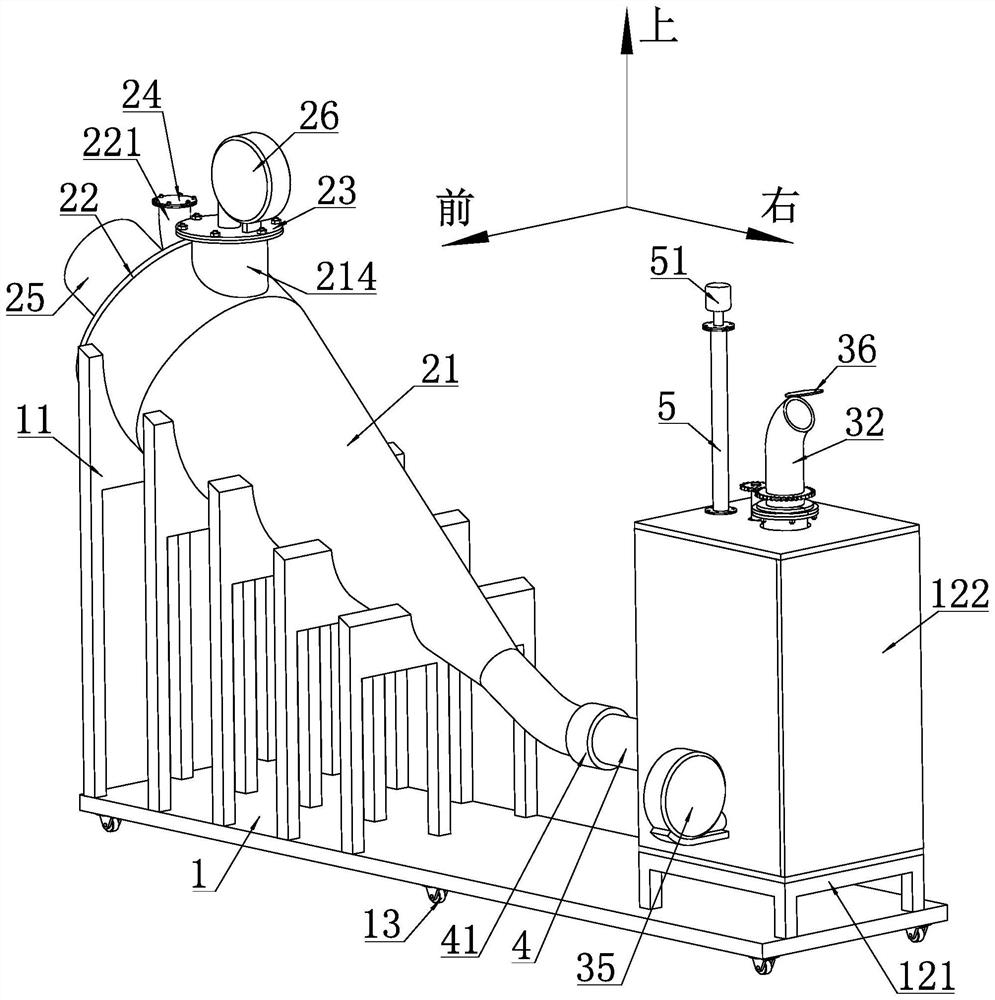
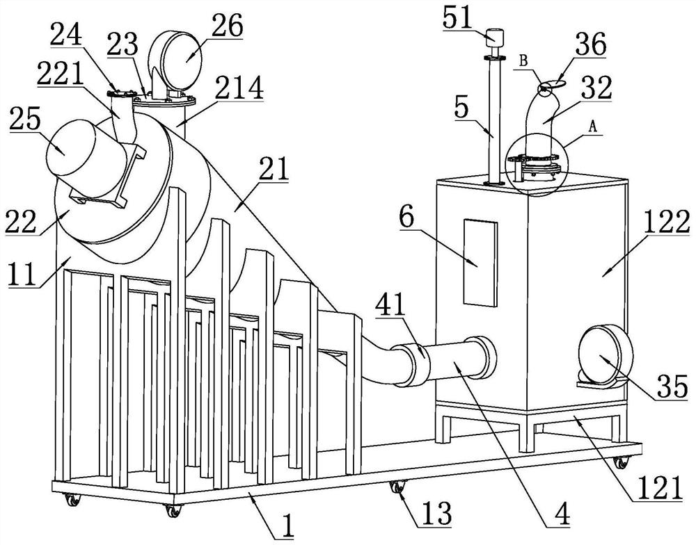
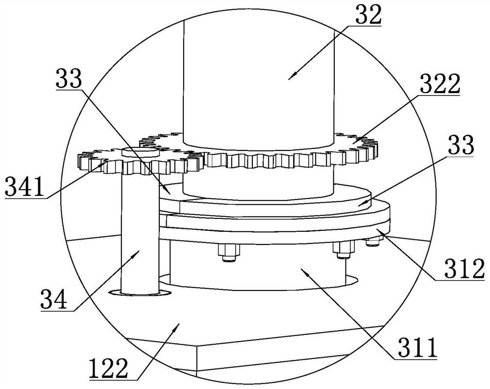
[0065] The second supporting frame includes an underframe 121 fixedly arranged on the bottom plate 1, and the underframe 121 includes a square frame formed by four side beams connected sequentially. The four sides of the square frame Outriggers extending downwards in the vertical direction are arranged on the corners, and the lower ends of the outriggers are fixedly provided with anchor plates by welding, and the anchor plates are fixedly connected with the bottom plate 1 by screws. The lower part of the pressurized tank 31 is fixedly provided with a square connecting plate by welding, and the connecting plate is fixedly connected with the side beam of the chassis 121 by screws, and the lower end of the pressurized tank 31 is inserted into into the square frame as described. A motor mounting plate is fixedly arranged on the discharge pipe 311 by welding, the rotating motor 34 is fixedly arranged on the motor mounting plate, and the power output shaft of the rotating motor 34 p...

Embodiment 3

[0067] The transmission mechanism includes a driving pulley fixedly arranged on the power output shaft of the rotary motor 34, a driven pulley is fixedly arranged on the powder spray pipe, and the driven pulley is connected with the timing belt through a synchronous belt. The driving pulley is connected, and all the other structures are the same as in Embodiment 1.

Embodiment 4

[0069] A plurality of stirring rods 2221 are arranged in a helical shape along the rotating shaft 222, and the rest of the structure is the same as the first embodiment.


PUM


Abstract

The invention discloses a gas automatic fire extinguishing device for a substation and relates to the technical field of substation fire protection equipment. It specifically includes a base plate, on which a raw material storage unit and a pressurized spraying unit are fixedly arranged in sequence from left to right. The raw material storage unit includes a storage tank, the left end of the storage tank is provided with a first cover plate, the storage tank is provided with a first air intake pipe, and the first air intake pipe is connected to the air outlet of the stirring fan. The pressurized spraying unit includes a pressurized tank and a rotating motor. The upper end of the pressurized tank is provided with a discharge pipe, and the upper end of the discharge pipe is rotated to be provided with a spray pipe. The outlet of the spray pipe faces outward and upward. The power output shaft of the rotary motor is connected with the nozzle through a transmission mechanism. The pressurized tank is connected with the outlet of the storage tank through a connecting pipe. The device is not only low in cost, but also convenient to move, can rationally arrange fire extinguishing points according to needs, and has good fire extinguishing effect.

Description

technical field [0001] The invention relates to the technical field of substation fire-fighting equipment, in particular to a gas automatic fire-extinguishing device for a substation. Background technique [0002] With the development of the country and the improvement of people's living standards, the electricity consumption of the society is also increasing year by year, and the substation is the hub of power transportation, and the safety of the substation is the top priority. Due to the large number of electrical components and complex wiring in substations, fires are most likely to occur. [0003] In order to meet the requirements of prevention first and combination of prevention and fire prevention, traditional substations generally implement fire protection by adopting gas-insulated closed combined electrical equipment (GIS) equipment, optimizing the plane layout of substations, and increasing the flash point of transformer oil. As far as fire extinguishing equipment...

Claims


Application Information

Patent Timeline
Patent Type & Authority Patents(China)
IPC IPC(8): A62C3/16A62C27/00A62C31/02A62C31/28A62C37/38
CPCA62C3/16A62C27/00A62C31/02A62C31/28A62C37/38
Inventor 谢丹陈庆伟姜海英王志鹏刘博朱元吉王文洋朱毅赵志鹏郭靖张鑫洪伟艺常世伟熊孝新蔺江赖顺生朱志明
Owner RES INST OF ECONOMICS & TECH STATE GRID SHANDONG ELECTRIC POWER
Why Eureka
Try Eureka