Eureka AIR delivers breakthrough ideas for toughest innovation challenges, trusted by R&D personnel around the world.

Cycloid rotor pump with unsmooth surfaces

A non-smooth surface, cycloid rotor pump technology, used in rotary piston pumps, rotary piston/oscillating piston pump components, pumps, etc., can solve the problem of reducing fast swimming resistance, reducing wall friction resistance, Affect the life of the pump and other problems, and achieve the effect of prolonging the time of filling oil, reducing vibration and noise, and preventing oil trapping.

Inactive Publication Date: 2016-08-03
ZHEJIANG UNIV OF TECH
View PDF9 Cites 1 Cited by
  • Summary
  • Abstract
  • Description
  • Claims
  • Application Information

AI Technical Summary

Problems solved by technology

Studies have shown that the scales on shark skin can stabilize the boundary layer and reduce the resistance of fast swimming. The special non-smooth surface structure of other cetaceans can also reduce drag when swimming. Inspired by this, we can change The surface shape of the object is used to change the flow field near the wall to reduce the frictional resistance of the wall; in addition, when the inner and outer rotors are in the meshing process, a closed space is formed due to the gap between the inner and outer rotors. As the rotor rotates, this The volume of the closed space changes, and the compressibility of the liquid is very small, so that the pressure of the liquid in the closed space suddenly rises, that is, the trapped oil pressure, which is much higher than the working pressure of the rot

Method used


Image

  • Cycloid rotor pump with unsmooth surfaces
  • Cycloid rotor pump with unsmooth surfaces
  • Cycloid rotor pump with unsmooth surfaces

Examples


Embodiment 1

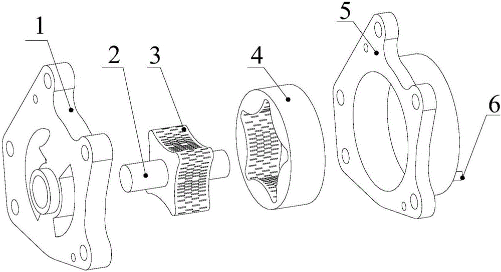
[0029] Embodiment 1 The cycloidal rotor pump with a non-smooth surface of the present invention includes an inner rotor 3, an outer rotor 4, a connecting shaft 2, a pump body 5, and a pump cover 1 fixed to the pump body. The inner rotor 3 is engaged with the outer rotor 4 installed in the cavity of the pump body 5, and the closed volume formed by the tooth gap between the inner rotor 3 and the outer rotor 4 is used as a working chamber; the inner rotor 3 is heated to 250°C, Use a press to press into the shaft 2, so that the connection shaft 2 and the inner rotor 3 are tightly connected. The end of the shaft 2 passing through the shaft hole of the pump body 5 is the input end, and the end of the connecting shaft 2 passing through the shaft hole of the pump cover 1 is the output end. The pump cover 1 is provided with an asymmetrical oil inlet groove 11 and The oil outlet groove 12, the oil inlet groove 11 and the oil outlet groove 12 are respectively communicated with the closed...


PUM


Abstract

The invention discloses a cycloid rotor pump with unsmooth surfaces. The cycloid rotor pump comprises an inner rotor, an outer rotor, a connecting shaft, a pump body and a pump cover fixedly connected with the pump body, wherein an oil inlet groove and an oil outlet groove with asymmetric shapes are formed in the pump cover; the oil inlet groove and the oil outlet groove communicate with sealed spaces; a pressure limiting valve is arranged on the pump body; the number of external teeth of the inner rotor is one smaller than the number of internal teeth of the outer rotor; the external tooth profile of the inner rotor and the internal tooth profile of the outer rotor are a pair of conjugate curves, and the teeth are in engagement state; at least one line of inner rotor bionic unsmooth structures are arranged on the outer wall surface of the inner rotor in the circumferential direction; and at least one line of outer rotor bionic unsmooth structures are arranged on the inner wall surface of the outer rotor in the circumferential direction. The cycloid rotor pump has the beneficial effects that the inner rotor and the outer rotor adopt unsmooth surfaces based on bionics principle, additional devices and space occupation are not required, pollution is not caused to a fluid, a relatively good resistance reducing effect can be achieved only through directly changing the shapes of the wall surfaces, the energy loss is reduced, and environmental protection and energy saving are achieved.

Description

technical field [0001] The invention relates to a cycloid rotor pump, in particular to a cycloid rotor pump with a non-smooth surface. Background technique [0002] The cycloidal rotor pump is widely used in the lubrication system of vehicles and ship equipment due to its advantages of compact structure, stable operation, small pulsation and high volumetric efficiency. Nowadays, many high-speed medium and large internal combustion engines also generally use cycloidal rotor pumps, which require a large amount of oil supplied by the pump, so the pump size is also large, the pump teeth are thickened, and it takes longer for the oil to fill the pump oil chamber. [0003] At present, energy saving and emission reduction have become the first choice for technology upgrading in the entire automobile industry. At present, the oil pump of the engine has great potential for energy saving. The field presents a three-dimensional unsteady turbulent flow, and the viscosity of the oil is ...

Claims


Application Information

Patent Timeline
IPC IPC(8): F04C2/10F04C15/00
CPCF04C2/10F04C2/084F04C15/0088F04C2240/20
Inventor 牟介刚陈真富谷云庆范天星吴登昊周佩剑张韬唐佳新吴振兴
Owner ZHEJIANG UNIV OF TECH
Why Eureka
Eureka Blog
Learn More