A Distributed Matching Antenna Device

An antenna device and distributed technology, applied in the field of communication, can solve the problems of high and low frequency mutual interference, difficulty in taking into account at the same time, poor quality of low frequency bandwidth, etc., and achieve the effect of improving matching efficiency

Active Publication Date: 2018-10-19
VIVO MOBILE COMM CO LTD
View PDF9 Cites 0 Cited by
  • Summary
  • Abstract
  • Description
  • Claims
  • Application Information

AI Technical Summary

Problems solved by technology

[0005] This application provides a distributed matching antenna device to solve the problems of high and low frequency mutual interference, difficulty in taking care of both at the same time, and poor quality of low frequency bandwidth

Method used


Image

  • A Distributed Matching Antenna Device
  • A Distributed Matching Antenna Device
  • A Distributed Matching Antenna Device

Examples


Embodiment 1

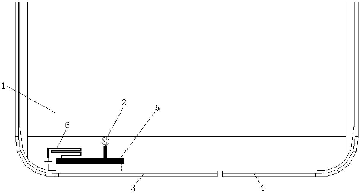
[0045] refer to figure 1 , shows a schematic structural diagram of a distributed matching antenna device in Embodiment 1 of the present application. In this embodiment, the distributed antenna device includes: a main board 1 , a feed source 2 , a first metal support arm 3 , a second metal support arm 4 , an antenna coupling piece 5 and a first tuning device 6 .

[0046] Such as figure 1 As shown, the first metal support arm 3 and the second metal support arm 4 are arranged on the same straight line, and the end of the first metal support arm 3 and the end 4 of the second support arm meet a set interval. It should be noted that the set interval can be understood as a breakpoint usually set during the antenna parameter tuning process. The length of the first metal support arm 3 is greater than the length of the second metal support arm 4 . The longer first metal arm 3 generates low frequency resonance and high frequency second resonance, and the shorter second metal arm 4 gen...

Embodiment 2

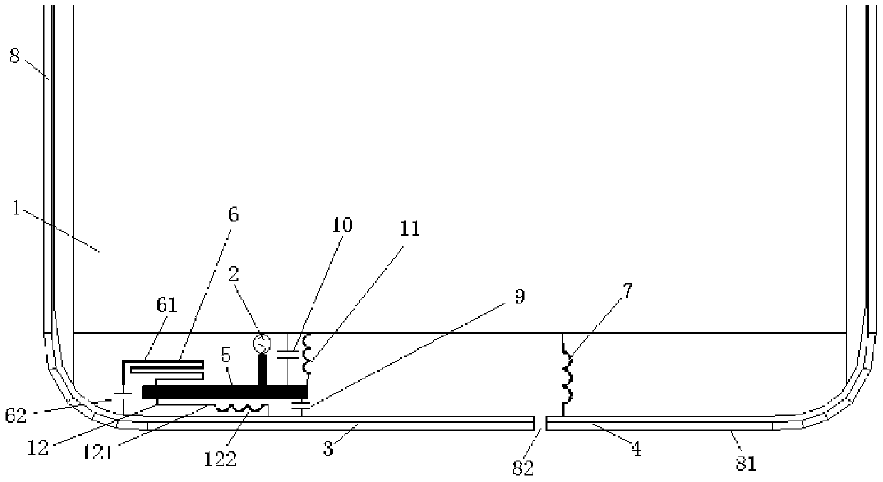
[0052] refer to figure 2 , shows a schematic structural diagram of a distributed matching antenna device in Embodiment 2 of the present application. In this embodiment, the distributed matching antenna device includes: a main board 1, a feed source 2, a first metal arm 3, a second metal arm 4, an antenna coupling piece 5, a first tuning device 6 and a first Inductance7.

[0053] Such as figure 2 As shown, preferably, the antenna device further includes: a frame 8 . The main board 1 is arranged in the frame 8 . It should be noted that the frame 8 may be a metal frame (that is, the first frame), or a non-metal frame (that is, the second frame). The frame 8 may be of any suitable shape, for example, a rectangular frame commonly used by mobile terminals at present.

[0054] by figure 2 The rectangular border shown is used as an example to illustrate:

[0055] If the frame 8 is a metal frame (first frame), one of the short sides 81 of the frame 8 can be selected as the fi...


PUM


Abstract

Provided is a distributed matching antenna device, comprising: a mainboard, a feed source, a first metal support arm, a second metal support arm, an antenna coupling sheet and a first tuning device. The first metal support arm and the second metal support arm are arranged on the same straight line. A set gap is provided between an end of the first metal support arm and an end of the second support arm. The length of the first metal support arm is greater than the length of the second metal support arm. The antenna coupling sheet is disposed between the feed source and the first metal support arm. One side of the antenna coupling sheet is connected to the feed source, and the other side of the antenna coupling sheet is coupled with the first metal support arm. The first tuning device is disposed between the antenna coupling sheet and the first metal support arm, and is connected to the antenna coupling sheet and the first metal support arm respectively.

Description

technical field [0001] The present application relates to the technical field of communication, and in particular to a distributed matching antenna device. Background technique [0002] In the development process of existing mobile terminals, the products are all developing in the direction of thinner and stronger metal texture, and the thinner and stronger metal texture handheld terminal equipment undoubtedly brings a huge challenge to the design of the antenna. How to ensure the quality of the antenna signal is thin and has a strong metal texture in the design process of handheld terminal equipment, which has always been a difficult problem in the industry. [0003] At present, in order to ensure the quality of the antenna signal in the thin and metallic handheld terminal device, a commonly used design solution is to provide a coupling-feed antenna device in the thin and metallic handheld terminal device. Wherein, the coupling feed-in antenna device adopts a metal ornamen...

Claims


Application Information

Patent Timeline
Patent Type & Authority Patents(China)
IPC IPC(8): H01Q5/50H01Q1/22H01Q23/00H01Q1/44
CPCH01Q1/24
Inventor 陈玉稳
Owner VIVO MOBILE COMM CO LTD
Why Eureka
Try Eureka